
Page 367 - Trenchless Technology Piping Installation and Inspection
P. 367
Inspection and QA/QC for Trenchless Installation and Replacement Methods 317
rates, bag samples of soils from separation plant, and unusual prob-
lems encountered during excavation must be conducted.
Post–QA/QC Assessment
The visual inspection of microtunneling installations includes line
and grade, joints, pipe damages (such as cracks, joints shoving, and
so on), deformations, lateral connections, and linings and coatings
(if available). The pipe’s grade and alignment must be checked
against plans/specifications and the pipe must be tested for joint
integrity and design pressure.
Acceptance tests of nonaccessible pipes are carried out by means
of closed circuit television (CCTV) technology according to NASSCO
guidelines or laser inspection or other methods. For flexible jacking
pipes (such as GRP and steel) the deformation is to be checked regard-
ing its correspondence with acceptable tolerance limit set in the
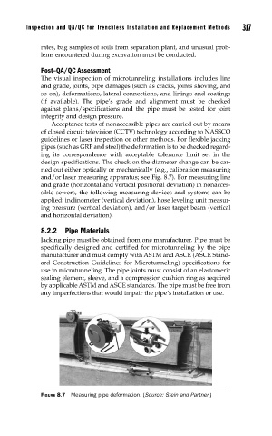
design specifications. The check on the diameter change can be car-
ried out either optically or mechanically (e.g., calibration measuring
and/or laser measuring apparatus; see Fig. 8.7). For measuring line
and grade (horizontal and vertical positional deviation) in nonacces-
sible sewers, the following measuring devices and systems can be
applied: inclinometer (vertical deviation), hose leveling unit measur-
ing pressure (vertical deviation), and/or laser target beam (vertical
and horizontal deviation).
8.2.2 Pipe Materials
Jacking pipe must be obtained from one manufacturer. Pipe must be
specifically designed and certified for microtunneling by the pipe
manufacturer and must comply with ASTM and ASCE (ASCE Stand-
ard Construction Guidelines for Microtunneling) specifications for
use in microtunneling. The pipe joints must consist of an elastomeric
sealing element, sleeve, and a compression cushion ring as required
by applicable ASTM and ASCE standards. The pipe must be free from
any imperfections that would impair the pipe’s installation or use.
FIGURE 8.7 Measuring pipe deformation. (Source: Stein and Partner.)