
Page 371 - Trenchless Technology Piping Installation and Inspection
P. 371
Inspection and QA/QC for Trenchless Installation and Replacement Methods 321
Pipe Installation
Profile and alignment of microtunneling operation must be shown on
the approved construction drawings. The contractor must grant the
engineer/inspector access to all data and printouts obtained from
MTBM, such as position of the MTBM, the fluid pressures, jacking
loads, and spoil removal.
Jacking Force Calculation
1. As a minimum, the estimated jacking force must not exceed
half or one-third of specified allowable jacking capacity of the
pipe to avoid pipe damage. Pipe manufacturer will provide
specific safety factor for the type of pipe used.
2. Influential factors for estimating jacking force include
• Length of the drive
• Weight, grade, and diameter of the pipe
• Height of the overburden
• Soil characteristics
• Water table and dewatering operations
• Calculated load on the shield (face pressure)
• Operational interruptions (i.e., consideration for swelling
of soil)
• Overcut size
• Lubrication
• Any operational change in line and grade
• Possible use of intermediate jacking stations
• Pipe material, its dimensional consistency and squareness
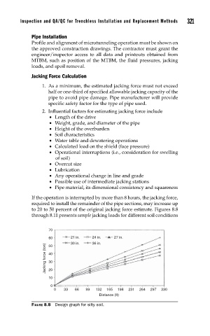
If the operation is interrupted by more than 8 hours, the jacking force,
required to install the remainder of the pipe sections, may increase up
to 20 to 50 percent of the original jacking force estimate. Figures 8.8
through 8.11 presents sample jacking loads for different soil conditions
70
60 21 in. 24 in. 27 in.
30 in. 36 in.
Jacking force (ton) 40
50
30
20
10
0
0 33 66 99 132 165 198 231 264 297 330
Distance (ft)
FIGURE 8.8 Design graph for silty soil.