
Page 366 - Trenchless Technology Piping Installation and Inspection
P. 366
316 Cha pte r Ei g h t
1 2
4 5 6 7
3
8
9
10
11
12 13
14 15
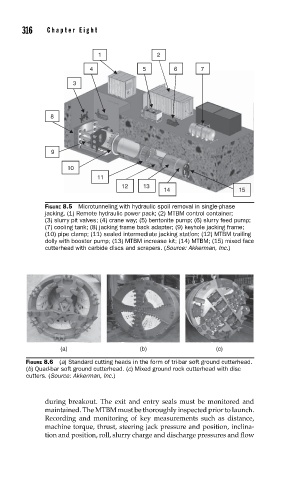
FIGURE 8.5 Microtunneling with hydraulic spoil removal in single-phase
jacking. (1) Remote hydraulic power pack; (2) MTBM control container;
(3) slurry pit valves; (4) crane way; (5) bentonite pump; (6) slurry feed pump;
(7) cooling tank; (8) jacking frame back adapter; (9) keyhole jacking frame;
(10) pipe clamp; (11) sealed intermediate jacking station; (12) MTBM trailing
dolly with booster pump; (13) MTBM increase kit; (14) MTBM; (15) mixed face
cutterhead with carbide discs and scrapers. (Source: Akkerman, Inc.)
(a) (b) (c)
FIGURE 8.6 (a) Standard cutting heads in the form of tri-bar soft ground cutterhead.
(b) Quad-bar soft ground cutterhead. (c) Mixed ground rock cutterhead with disc
cutters. (Source: Akkerman, Inc.)
during breakout. The exit and entry seals must be monitored and
maintained. The MTBM must be thoroughly inspected prior to launch.
Recording and monitoring of key measurements such as distance,
machine torque, thrust, steering jack pressure and position, inclina-
tion and position, roll, slurry charge and discharge pressures and flow