
Page 134 - Tribology in Machine Design
P. 134
120 Tribology in machine design
4.7.3. Power transmission rating
The friction torque transmitted by both clutch plates is
If M is expressed in Nm and N is the speed of the clutch in revolutions per
minute, then
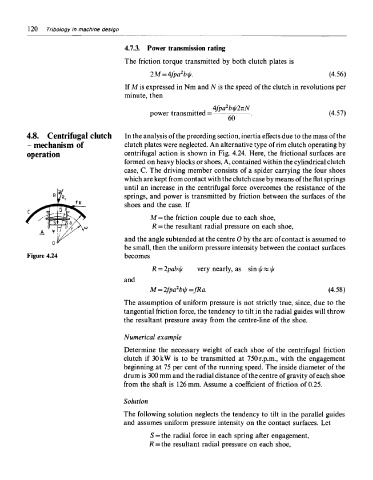
4.8. Centrifugal clutch In the analysis of the preceding section, inertia effects due to the mass of the
- mechanism of clutch plates were neglected. An alternative type of rim clutch operating by
operation centrifugal action is shown in Fig. 4.24. Here, the frictional surfaces are
formed on heavy blocks or shoes, A, contained within the cylindrical clutch
case, C. The driving member consists of a spider carrying the four shoes
which are kept from contact with the clutch case by means of the flat springs
until an increase in the centrifugal force overcomes the resistance of the
springs, and power is transmitted by friction between the surfaces of the
shoes and the case. If
M=the friction couple due to each shoe,
R = the resultant radial pressure on each shoe,
and the angle subtended at the centre 0 by the arc of contact is assumed to
be small, then the uniform pressure intensity between the contact surfaces
Figure 4.24 becomes
The assumption of uniform pressure is not strictly true, since, due to the
tangential friction force, the tendency to tilt in the radial guides will throw
the resultant pressure away from the centre-line of the shoe.
Numerical example
Determine the necessary weight of each shoe of the centrifugal friction
clutch if 30 kW is to be transmitted at 750 r.p.m., with the engagement
beginning at 75 per cent of the running speed. The inside diameter of the
drum is 300 mm and the radial distance of the centre of gravity of each shoe
from the shaft is 126 mm. Assume a coefficient of friction of 0.25.
Solution
The following solution neglects the tendency to tilt in the parallel guides
and assumes uniform pressure intensity on the contact surfaces. Let
S=the radial force in each spring after engagement,
R = the resultant radial pressure on each shoe,