
Page 229 - Tribology in Machine Design
P. 229
214 Tribology in machine design
Component forces on main bearings have been studied using the simple
crank arrangement shown in Fig. 5.32, where the crankshaft form displays a
mirror image about a line centrally disposed between two consecutive main
bearings, as shown by line x lx l in Fig. 5.33. There are, however, many other
cases where such a mirror image does not occur. For such cases the loads on
the main bearing may be obtained by taking moments, the crankshaft
bearing being treated as a number of simply supported beams resting
between supports at the main bearings. Two component reactions are
obtained at the main bearing D by considering the two consecutive lengths
of crankshaft CD and DE respectively. These component reactions (at D)
are then vectorially added together to obtain the main bearing load
reaction at the particular crank-angle position under consideration.
F,
8=360° . I
! L L K
; 2 J_ 2 t
I ~~ I .5 1.5
Figure 5.33 Xe 2 2
X. \ ///A \ffi/ft f " K^
\ . 1' I; I ~ I
Figure 5.32 9,120 2 2 k k
* 2 * 2
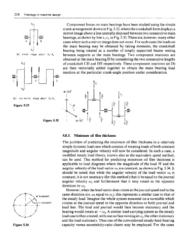
5.8.3. Minimum oil film thickness
The problem of predicting the minimum oil film thickness in a relatively
simple dynamic load case which consists of rotating loads of both constant
magnitude and angular velocity will now be considered. In such a case, a
modified steady load theory, known also as the equivalent speed method,
can be used. This method for predicting minimum oil film thickness is
applicable to load diagrams where the magnitude of the load W and the
angular velocity of the load vector coi are constant, as shown in Fig. 5.34. It
should be noted that while the angular velocity of the load vector MI is
constant, it is not necessary (for this method) that it be equal to the journal
angular velocity coj and furthermore that it may rotate in the opposite
direction to Wj.
However, when the load vector does rotate at the journal speed and in the
same direction (i.e. u>\ equal to coj), this represents a similar case to that of
the steady load. Imagine the whole system mounted on a turntable which
rotates at the journal speed in the opposite direction to both journal and
load line. The load and journal would then become stationary and the
bearing would rotate at — co-,. A similar load-carrying system as the steady
load case is then created, with one surface moving at Wj, the other stationary
and the load stationary. Thus one of the conventional steady-load-bearing
Figure 5.34 capacity versus eccentricity-ratio charts may be employed. For the cases