
Page 230 - Tribology in Machine Design
P. 230
Sliding-element bearings 215
where the load rotates at speeds other than the journal speed, a correction
may be made to the journal speed term to account for this.
If, however, a rigorous view is adopted about the equivalence of rotating-
load and steady-load cases, then it should be made apparent that oil
grooving in the bearing and/or oil feed holes in the journal will not give a
true similarity. Neither will the heat distribution in the bearing be the same.
For the rotating-load case all the bearing surface will be subjected to the
shearing of small oil films as the load passes over it, whereas for the steady
case, small films and associated high temperatures are confined to one local
region of the bearing. The bearing surface, at any" point, is subjected to
fluctuating developed pressure in the oil film due to the rotating load
although this load is of constant magnitude. Such a condition could give
rise to fatigue of the bearing material. These factors, although they may be
of secondary importance, illustrate that one must be aware of realities when
considering a so-called equivalent system.
We return to the equivalent speed method and consider a journal bearing
arrangement which has a rotating journal of constant angular velocity, coj, a
rotating load of constant magnitude and constant angular velocity, co,, and
a fixed or rotating bearing of constant angular velocity co b. The load-
carrying capacity of such a system is proportional to the average angular
velocity of the bearing and journal relative to the load line. This particular
case was discussed in more detail in Section 5.5.5. Thus
The load-carrying capacity for a steadily loaded bearing, although
proportional to coj, also depends on the bearing length L, diameter d, radial
clearance c and operating viscosity n in the bearing. These variables
together with the load W form a dimensionless load number S which is
given by
This is usually referred to as the Sommerfeld number and was derived in
Chapter 2. There are a number of cases where the load-carrying capacity
can be deduced from the load number. Thus: for steady load coi=0 the load
capacity is proportional to coj, for counter rotation coi=—o)j the load
capacity is proportional to 3cOj, for rotating in phase a>i=a>j the load
capacity is proportional to Wj, for a load rotating at half-speed <D\=o>j/2 the
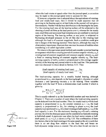
load capacity is zero. For the stationary bearing (co b=0) and a rotating
journal, the oil in the clearance space can be considered as basically rotating
at half-shaft-speed. A particular case when the load vector rotates at half-
shaft-speed, i.e. co!=cOj/2, is shown in Fig. 5.35. The combination of these
two factors, that is the load rotating at the same speed as the oil, is such that
there is no net drag flow relative to the load line and hence no
Figure 5.35 hydrodynamic wedge action is created. The oil is then forced out due to