
Page 232 - Tribology in Machine Design
P. 232
Sliding-element bearings 217
capacity for wedge action will occur in all the above cases when co/Wj is zero.
For a particular load diagram, use of this fact can be made by plotting oj/a> }
against the crank angle 0 and noting when this value is small compared
with the load W. If this should happen for a comparatively long period
during the load cycle, then a squeeze interval is predominant and squeeze
action theory can be applied as an approximation for the solution of
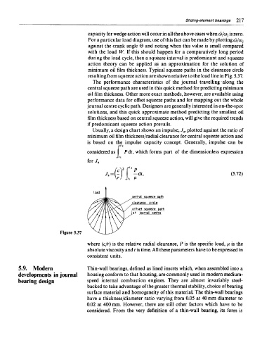
minimum oil film thickness. Typical squeeze paths in the clearance circle
resulting from squeeze action are shown relative to the load line in Fig. 5.37.
The performance characteristics of the journal travelling along the
central squeeze path are used in this quick method for predicting minimum
oil film thickness. Other more exact methods, however, are available using
performance data for offset squeeze paths and for mapping out the whole
journal centre cyclic path. Designers are generally interested in on-the-spot
solutions, and this quick approximate method predicting the smallest oil
film thickness based on central squeeze action, will give the required trends
if predominant squeeze action prevails.
Usually, a design chart shows an impulse, J a, plotted against the ratio of
minimum oil film thickness/radial clearance for central squeeze action and
is based on the impulse capacity concept. Generally, impulse can be
r
considered as Pdt, which forms part of the dimensionless expression
Jfi
for J a
Figure 5.37
where (c/r) is the relative radial clearance, P is the specific load, \JL is the
absolute viscosity and t is time. All these parameters have to be expressed in
consistent units.
5.9. Modern Thin-wall bearings, defined as lined inserts which, when assembled into a
developments in journal housing conform to that housing, are commonly used in modern medium-
bearing design speed internal combustion engines. They are almost invariably steel-
backed to take advantage of the greater thermal stability, choice of bearing
surface material and homogeneity of this material. The thin-wall bearings
have a thickness/diameter ratio varying from 0.05 at 40 mm diameter to
0.02 at 400 mm. However, there are still other factors which have to be
considered. From the very definition of a thin-wall bearing, its form is