
Page 231 - Tribology in Machine Design
P. 231
216 Tribology in machine design
squeeze action. For the case when the value of both coi and W are changing
with time, the equivalent speed method, using a steady load-capacity
relationship, is not applicable. There are several ways to demonstrate that
this is the case. For instance if co, happened to pass through a half-speed
load vector condition almost instantaneously, the equivalent speed method
would give zero oil film thickness at that instant. In practice, however, the
oil cannot be squeezed out of the bearing instantaneously. It takes time,
during which the load vector has changed and the half-speed vector no
longer exists. Another point which is often overlooked is, that the position
and direction of motion of the journal centre in the bearing, depend on the
velocity variation of the journal centre along its path. Such variations are
not taken into account in the equivalent speed method. In consequence, this
method which relies on wedge action should not be used to predict oil film
thickness in engine bearings where the load and (o\ are varying. The above
method is, however, useful to indicate in an approximate manner, where
periods of zero load capacity due to collapse of the wedge action exist and
during such periods squeeze-action theory can be applied.
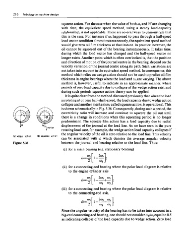
It is quite clear from the method discussed previously that when the load
is rotating at or near half-shaft-speed, the load capacity due to wedge action
collapse and another mechanism, called squeeze action, is operational. This
is shown schematically in Fig. 5.36. Consequently, during such a period, the
eccentricity ratio will increase and continue to squeeze the oil out until
there is a change in conditions when this squeezing period is no longer
predominant. The squeeze film action has a load capacity due to radial
displacement of the journal at the load line. As we have seen in the pure
rotating load case, for example, the wedge action load capacity collapses if
the angular velocity of the oil is zero relative to the load line. This velocity
can be associated with co which denotes the average angular velocity
Figure 5.36 between the journal and bearing relative to the load line. Thus:
(i) for a main bearing (e.g. stationary bearing)
(ii) for a connecting-rod bearing where the polar load diagram is relative
to the engine cylinder axis
(iii) for a connecting-rod bearing where the polar load diagram is relative
to the connecting-rod axis,
Since the angular velocity of the bearing has to be taken into account in a
big-end connecting-rod bearing, one should not consider coi/coj equal to 0.5
as indicating collapse of the load capacity due to wedge action. Zero load