
Page 236 - Tribology in Machine Design
P. 236
Sliding-element bearings 221
between the shaft and the lining material becomes important. Rig tests to
establish the relative compatibility rates of various compositions of
tin-aluminium and copper-lead verify the superiority of the tin-
aluminium.
The large slow-speed direct-drive engines still principally use white-
metal lined bearings, although more commonly these are thin-wall bearings,
but predominantly overlay-plated to gain the benefits mentioned earlier.
Tin-aluminium, however, and in some instance copper-lead are increas-
ingly being adopted, and as with medium-speed engines, this will become
more and more usual to take advantage of the higher fatigue strength of
white-metal linings. It is considered that the more compatible, corrosion
resistant high tin-aluminium alloys will be the more satisfactory in these
engine types.
5.10. Selection and Thrust bearings come in two distinct types, which involve rather different
design of thrust bearings technical levels; first, the bearing which is mainly an end-clearance limiting
or adjusting device, and second, a bearing which has to carry a heavy load.
A typical example of the first type is the bearing used to locate the
crankshaft of the reciprocating engine. The loading in these bearings is not
usually known with any reasonable accuracy, arising as it does from shocks
or tilting of the engine.
It is obviously advantageous to take advice of a bearing manufacturer
regarding material and maximum loading, however, the most practical
approach is usually to be guided by past experience and comparable
machines, but to allow space for possible future modifications in the light of
further experience. Bearings of this kind are no longer made by lining a
casing with white metal. It is an almost universal practice to stamp
complete rings or half-rings from steel-backed strip, faced with white metal,
overlay-plated copper-lead, aluminium-tin or one of the self-lubricating or
dry-running bearing composition materials. These rings can then be
removed if necessary without disturbing the main shaft. In the past, thrust
rings - often of solid bronze - were prevented from rotation by means of
deeply countersunk screws that secured them to the housings. The current
trend, however, is to clamp them into undercut recesses by tightening down
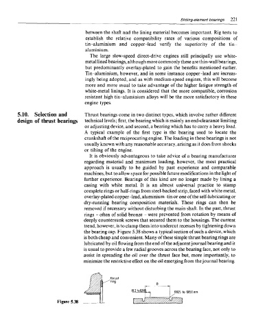
the bearing cap. Figure 5.38 shows a typical section of such a device, which
is both cheap and convenient. Many of these simple thrust bearing rings are
lubricated by oil flowing from the end of the adjacent journal bearing and it
is usual to provide a few radial grooves across the bearing face, not only to
assist in spreading the oil over the thrust face but, more importantly, to
minimize the restrictive effect on the oil emerging from the journal bearing.
J Pin9 B
thrust
^
'0-2toa3)k
I ,/ 0.025 to Q050 mm
Figure 5.38 JLL i%^fe<%