
Page 291 - Tribology in Machine Design
P. 291
276 Tribology in machine design
is formed between the surfaces in contact. The friction and wear is
mainly controlled by the adsorbed surface film, a few Angstroms thick,
formed by the lubricant and its additives.
(ii) Mixed lubrication. The mixed lubrication regime is predominant when
the velocity of the gears is sufficient to develop a lubricating film but its
thickness does not provide full separation of the contacting surfaces.
As a result of that, direct contact between the highest asperities takes
place which may lead to accelerated running-in. The magnitude of the
frictional force and the rate of wear are significantly lower than in the
case of boundary lubrication.
(iii) Thick film lubrication. When the speed of the gears attains a
sufficiently high value, an elastohydrodynamic film is developed, the
thickness of which is adequate to separate completely the surfaces of
two teeth in mesh. In principle all the friction resistance comes from the
shearing of the elastohydrodynamic film. There is practically no wear if
a small amount of initial wear during running-in is ignored. The only
potential sources of wear in this lubrication regime are those due to
abrasive particles contaminating the oil and the surface fatigue
resulting in pitting. Each of the lubrication regimes can be assigned a
characteristic value of friction coefficient. In boundary lubrication,
a friction coefficient as high as 0.10-0.20 is not unusual. However,
when care is taken of the surface finish of the gear teeth and a good
boundary lubricant is used, the coefficient of friction can be substan-
tially reduced to, say, the 0.05-0.10 range. Mixed lubrication is
characterized by a coefficient of friction in the range of 0.04-0.07.
Thick film lubrication produces the lowest friction and a coefficient of
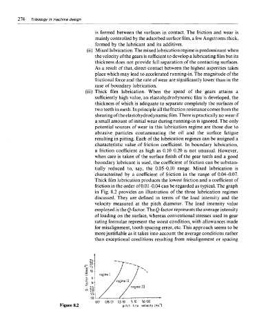
friction in the order of 0.01-0.04 can be regarded as typical. The graph
in Fig. 8.2 provides an illustration of the three lubrication regimes
discussed. They are defined in terms of the load intensity and the
velocity measured at the pitch diameter. The load intensity value
employed is the ^-factor. The Q-factor represents the average intensity
of loading on the surface, whereas conventional stresses used in gear
rating formulae represent the worst condition, with allowances made
for misalignment, tooth spacing error, etc. This approach seems to be
more justifiable as it takes into account the average conditions rather
than exceptional conditions resulting from misalignment or spacing
Figure 8.2