
Page 292 - Tribology in Machine Design
P. 292
Lubrication and efficiency of involute gears 277
errors. Any unusual load concentration will be relieved due to
running-in and the average conditions of loading will prevail.
The other important variable is the velocity measured at the pitch
diameter. The usual practice is to use the relative velocities of rolling and
sliding in any analysis, as they are responsible, among other factors, for
developing an oil film. In a first attempt, however, aimed at finding the
lubrication regime, the velocity of rolling at the pitch diameter can be used.
The upper limit in the Fig. 8.2 represents the approximate highest intensity
of tooth loading that case-carburized gears are able to carry. It also
represents the surface fatigue strength upper limit for a relatively good
design. It is well known that the pitting of gear teeth is markedly influenced
by the quality of the lubrication. Under thick film lubrication conditions
the S-N curve characterizing the tendency of gear teeth to pit is quite flat.
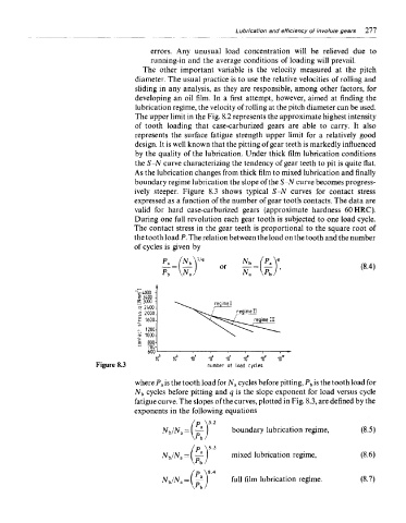
As the lubrication changes from thick film to mixed lubrication and finally
boundary regime lubrication the slope of the S-N curve becomes progress-
ively steeper. Figure 8.3 shows typical S-N curves for contact stress
expressed as a function of the number of gear tooth contacts. The data are
valid for hard case-carburized gears (approximate hardness 60HRC).
During one full revolution each gear tooth is subjected to one load cycle.
The contact stress in the gear teeth is proportional to the square root of
the tooth load P. The relation between the load on the tooth and the number
of cycles is given by
Figure 8.3
where P a is the tooth load for N a cycles before pitting, P b is the tooth load for
N b cycles before pitting and q is the slope exponent for load versus cycle
fatigue curve. The slopes of the curves, plotted in Fig. 8.3, are defined by the
exponents in the following equations
boundary lubrication regime,
mixed lubrication regime,
full film lubrication regime.