
Page 295 - Tribology in Machine Design
P. 295
280 Tribology in machine design
8.4.1. Critical temperature factor
The idea that scuffing is triggered when the temperature in the contact zone
exceeds a certain critical temperature was first introduced by Blok in 1937.
Failure of the lubricant film due to too high a temperature developed at the
points of real contact between two teeth in mesh is central to this
hypothesis. Contacting surface asperities form instantaneous adhesive
junctions which are immediately ruptured because of the rolling and sliding
of the meshing gears. This mechanism usually operates with gear teeth
running in a thick film lubrication regime.
A severe form of scuffing is usually accompanied by considerable wear
and as a result of that the teeth become overloaded around the pitch line. A
practical consequence of this is pitting in an accelerated form leading to
tooth fracture. One of the objectives the designer of gears must attain is to
secure their operation without serious scuffing. It is generally accepted that
a mild or light form of scuffing may be tolerated, provided it stops and the
gears recover. Simple measures such as changing to a more efficient oil,
operating the gears at less than service load until the completion of the
running-in of the teeth or even removing bad spots on large teeth by hand
can often be very effective in saving the gear drive from serious scuffing
problems.
A commonly used design procedure to avoid scuffing because of
excessively high temperature in the contact zone depends on the flash
temperature estimation which in turn is compared with the maximum
allowable temperature for a given oil. The approximate formula used to
estimate flash temperature is
where T { is the flash temperature index [°C], T b is the gear bulk
temperature [°C], b is the face width in contact [mm], m is the module
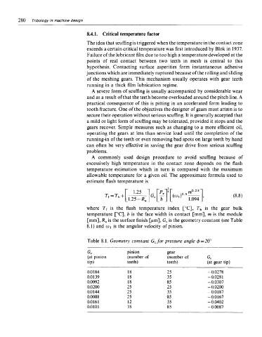
[mm], R a is the surface finish [/im], G c is the geometry constant (see Table
8.1) and CD I is the angular velocity of pinion.
Table 8.1. Geometry constant G cfor pressure angle $ = 20°
pinion gear
G c
(at pinion (number of (number of G c
tip) teeth) teeth) (at gear tip)
0.0184 18 25 -0.0278
0.0139 18 35 -0.0281
0.0092 18 85 -0.0307
0.0200 25 25 -0.0200
0.0144 25 35 -0.0187
0.0088 25 85 -0.0167
0.0161 12 35 -0.0402
0.0101 35 85 -0.0087