
Page 103 - Tunable Lasers Handbook
P. 103
84 Charles Freed
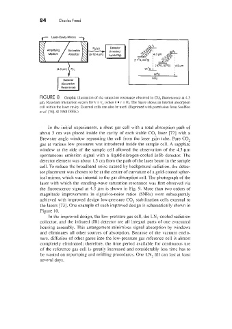
r Laser-Cavity Mirrors 7
4
(4.3~) PFL
Detector
(Saturation
Resonance)
FIGURE 8 Graphic illustration of the saturation resonance observed in CO, fluorescence at 4.3
pm. Resonant interaction occurs for v = vo (when k 1’ = 0). The figure shows an internal absorption
cell within the laser cavity. External cells can also be used. (Reprinted with permission from SooHoo
et d. [76]. 0 1985 IEEE.)
In the initial experiments. a short gas cell with a total absorption path of
about 3 cm was placed inside the cavity of each stable CO, laser [72] with a
Brewster angle window separating the cell from the laser g& tube. Pure CO,
gas at various low pressures was introduced inside the sample cell. A sapphire
window at the side of the sample cell allowed the observation of the 4.3-pm
spontaneous emission signal with a liquid-nitrogen-cooled InSb detector. The
detector element was about 1.5 cm from the path of the laser beam in the sample
cell. To reduce the broadband noise caused by background radiation. the detec-
tor placement was chosen to be at the center of curvature of a gold-coated spher-
ical mirror, which was internal to the gas absorption cell. The photograph of the
laser with which the standing-wave saturation resonance was first observed via
the fluorescence signal at 4.3 pm is shown in Fig. 9. More than two orders of
magnitude improvements in signal-to-noise ratios (SNRs) were subsequently
achieved with improved design low-pressure CO, stabilization cells external to
the lasers [73]. One example of such improved design is schematically shown in
Figure 10.
In the improved design, the low-pressure gas cell, the LN,-cooled radiation
collector, and the infrared (IR) detector are all integral partsbf one evacuated
housing assembly. This arrangement minimizes signal absorption by windows
and eliminates all other sources of absorption. Because of the vacuum enclo-
sure. diffusion of other gases into the low-pressure gas reference cell is almost
completely eliminated; therefore, the time period available for continuous use
of the reference gas cell is greatly increased and considerably less time has to
be wasted on repumping and refilling procedures. One LN, fill can last at least
several days.