Page 432 - Tunable Lasers Handbook
P. 432
392     Paul Zorabedian


                   With special mirror coating technology. the finesse of an etalon can be as high as
                   =10,000, but a finesse of a few hundred is more typically achieved with conven-
                   tional coatings.

                   7.2.1.4 Interference Filter
                      A bandpass interference filter is a multilayer thin-film device [66]. The sim-
                   plest type is really a Fabry-Perot  etalon with d - h. If the thickness of an etalon
                   is made very small, the orders will be widely separated. This is done by  evapo-
                   rating dielectric-stack mirrors, separated by a half-wave spacer layer, in a contin-
                   uous coating run on a substrate. Multiple reflector pairs (called cavities) can be
                   deposited to steepen the passband. Additional metallic-layer blocking stmctures
                   deposited on  another plate  are used to  eliminate adjacent transmission orders.
                   The plates are assembled in a sandwich that protects the deposited films. Inter-
                   ference  filters can be  made  with FWHM bandwidths 2 nm or less  in the near
                   infrared and less than  1 nm in the visible. The peak transmittance can be made
                   as high as 50 to 70%.
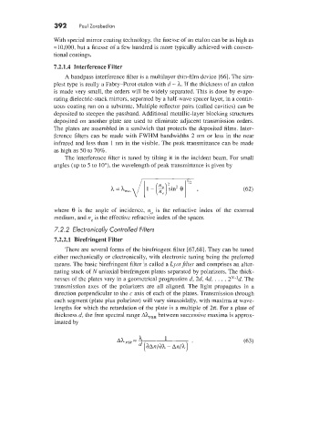
                      The interference filter is tuned by  tilting it in the incident beam. For small
                   angles (up to 5 to loo). the wavelength of peak transmittance is given by


                   where  8  is  the  angle  of  incidence,  izo  is  the  refractive  index  of  the  external
                   medium, and lie is the effective refractive index of the spacer.
                   7.2.2 Electronically Controlled Filters
                   7.2.2.1  Birefringent Filter
                      There are several forms of the birefringent filter [67,68]. They can be tuned
                   either mechanically or electronically, with electronic tuning being the preferred
                   means. The basic birefringent filter is called a Lyotfiltel- and comprises an alter-
                   nating stack of N  uniaxial birefringent plates separated by polarizers. The thick-
                   nesses of the plates vary in a geometrical progression d, 2d, 4d, . . . . 2”-’d.  The
                   transmission  axes  of  the  polarizers  are  all  aligned.  The  light  propagates  in  a
                   direction perpendicular to the c axis of each of the plates. Transmission through
                   each segment (plate plus polarizer) will vary sinusoidally, with maxima at wave-
                   lengths for which the retardation of the plate is a multiple of  2x. For a plate of
                   thickness d, the free spectral range Ah,,,  between successive maxima is approx-
                   imated by

                                              h
                                       Ah FSR   -      1
                                                (dAn/dh - An/h)

