
Page 433 - Tunable Lasers Handbook
P. 433
8 Tunable External-Cavity Semiconductor Lasers 393
For each segment, the separation between transmission maxima and the FWNM
of one of the maxima is inversely proportional to the plate thickness. Thus, the
resulting ti-ansmission spectrum for the entire stack will consist of narrow bands
having the FWHM of the thickest plate and separated by the free spectral range
of the thinnest plate. Electronically tuned birefringent filters can be realized
using liquid crystal cells as the birefringent plates [69,70]. The electro-optic
effect can also be used, either in bulk crystals [7 I] or in birefringent lithium nio-
bare waveguides [72],
7.2.2.2 Acousto-Optic Tunable Filter
7.2.2.2.1 Principle of Operation
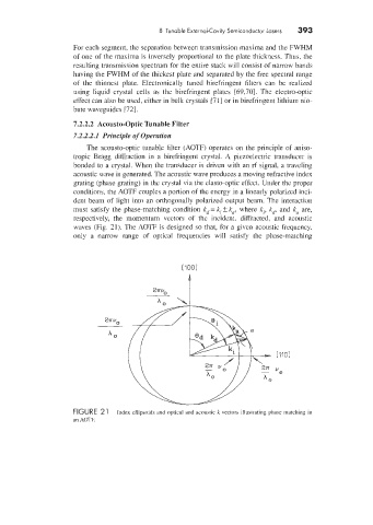
The acousto-optic tunable filter (AOTF) operates on the principle of aniso-
tropic BrBgg diffraction in a birefringent crystal. A piezoelectric transducer is
bonded to a crystal. When the transducer is driven with an rf signal, a traveling
acoustic wave is generated. The acoustic w'ave produces a moving refractive index
grating (phase grating) in the crystal via the elasto-optic effect. Under the proper
conditions, the AOTF couples a portion of the energy in a linearly polarized inci-
dent beam of light into an orthogonally polarized output beam. The interaction
must satisfy the phase-matching condition k - kl & k,, where k,, k8 and k, are,
dT
respectively, the momentum vectors of the incident, diffracted, and acoustic
waves (Fig, 31). The AOTF is designed so that, for a given acoustic frequency.
only a narrow range of optical frequencies will satisfy the phase-matching
P
FIGURE 2 1 Index ellipsoids and optical and acoustic k vectors illustrating phase matching in
an .40TF.