
Page 436 - Tunable Lasers Handbook
P. 436
396 Paul Zorabedian
!2.0
Wavelength (nm)
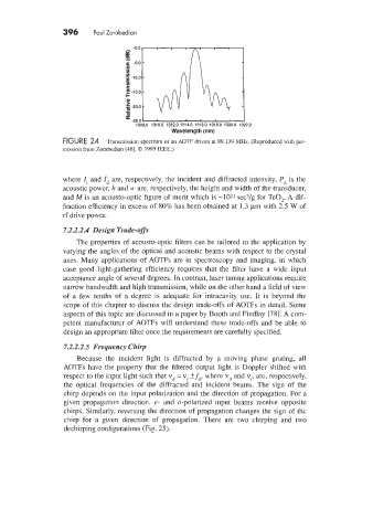
FIGURE 24 Transmission spectrum of an AOTF driven at 89.139 MHz. (Reproduced with per-
mission from Zorabedian [46]. 0 1995 IEEE.)
where I, and Id are, respectively, the incident and diffracted intensity, Pa is the
acoustic power, h and 1.1’ are, respectively, the height and width of the transducer,
and M is an acousto-optic figure of merit which is -1021 sec3/g for TeO,. A dif-
fraction efficiency in excess of 80% has been obtained at 1.3 pm with 5.5 W of
rf‘ drive power.
7.2.2.2.4 Design Trade-offs
The properties of acousto-optic filters can be tailored to the application by
varying the angles of the optical and acoustic beams with respect to the crystal
axes. Many applications of AOTFs are in spectroscopy and imaging, in which
case good light-gathering efficiency requires that the filter have a wide input
acceptance angle of several degrees. In contrast, laser tuning applications require
narrow bandwidth and high transmission, while on the other hand a field of view
of a few tenths of a degree is adequate for intracavity use. It is beyond the
scope of this chapter to discuss the design trade-offs of AOTFs in detail. Some
aspects of this topic are discussed in a paper by Booth and Findlay [78]. A com-
petent manufacturer of AOTFs will understand these trade-offs and be able to
design an appropriate filter once the requirements are carefully specified.
7.2.2.2.5 Frequency Chirp
Because the incident light is diffracted by a moving phase grating, all
AOTFs have the property that the filtered output light is Doppler shifted with
respect to the input light such that vd = vI k fa, where vd and vI, are, respectively,
the optical frequencies of the diffracted and incident beams. The sign of the
chirp depends on the input polarization and the direction of propagation. For a
given propagation direction. e- and o-polarized input beams receive opposite
chirps. Similarly. reversing the direction of propagation changes the sign of the
chirp for a given direction of propagation. There are two chirping and two
dechirping configurations (Fig. 25).