
Page 434 - Tunable Lasers Handbook
P. 434
394 Paul Zorabedian
condition. Thus, the AOTF is functionally an rf-controlled narrow-band optical
polarization converter. Changing the acoustic drive frequency shifts the band of
optical wavelengths for which the optical polarization is flipped. Separation of the
diffracted light from the residual undiffracted zeroth-order component results in
an electronically controlled optical filtering operation.
7.2.2.2.2 Acousto-Optic Filter Geometries
The first AOTF was invented by Harris and Nieh [73]. This device had a
geometry in which both optical beams were collinear with the acoustic beam.
This necessitated immersion in index matching oil [74] in order to bring the
optical and acoustic beams into collinearity and properly terminate the acoustic
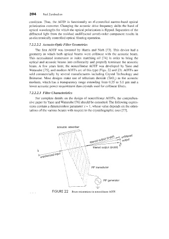
beam. A few years later, the noncollinear AOTF was developed by Yano and
Watanabe [75], and modem '40TFs are of this type (Figs. 22 and 23). AOTFs are
sold commercially by several manufacturers including Crystal Technology and
Brimrose. Most designs make use of tellurium dioxide (TeO,) as the acoustic
medium, which has a transparency range extending from 0.35 to 5.0 pm and a
lower acoustic power requirement than crystals used for collinear filters.
7.2.2.2.3 Filter Characteristics
For complete details on the design of noncollinear AOTFs. the comprehen-
sive paper by Yano and Watanabe [76] should be consulted. The following expres-
sions contain a dimensionless parameter x = 1. whose value depends on the orien-
tations of the various beams with respect to the crystallographic axes [77].
acoustic absorber
unfi\tered
output
RF transducer
-
-
FIGURE 22 Beam orientations in noncollinearI1\OTF.