
Page 21 - Understanding Automotive Electronics
P. 21
2735 | CH 1 Page 8 Tuesday, March 10, 1998 10:52 AM
1 AUTOMOTIVE FUNDAMENTALS
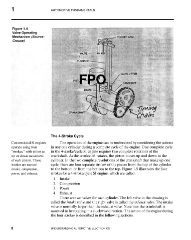
Figure 1.4
Valve Operating
Mechanism (Source:
Crouse)
FPO
The 4-Stroke Cycle
Conventional SI engines The operation of the engine can be understood by considering the actions
operate using four in any one cylinder during a complete cycle of the engine. One complete cycle
“strokes,” with either an in the 4-stroke/cycle SI engine requires two complete rotations of the
up or down movement crankshaft. As the crankshaft rotates, the piston moves up and down in the
of each piston. These cylinder. In the two complete revolutions of the crankshaft that make up one
strokes are named cycle, there are four separate strokes of the piston from the top of the cylinder
intake, compression, to the bottom or from the bottom to the top. Figure 1.5 illustrates the four
power, and exhaust. strokes for a 4-stroke/cycle SI engine, which are called:
1. Intake
2. Compression
3. Power
4. Exhaust
There are two valves for each cylinder. The left valve in the drawing is
called the intake valve and the right valve is called the exhaust valve. The intake
valve is normally larger than the exhaust valve. Note that the crankshaft is
assumed to be rotating in a clockwise direction. The action of the engine during
the four strokes is described in the following sections.
8 UNDERSTANDING AUTOMOTIVE ELECTRONICS