
Page 306 - Understanding Automotive Electronics
P. 306
2735 | CH 8 Page 293 Tuesday, March 10, 1998 1:19 PM
VEHICLE MOTION CONTROL 8
In this illustration, the front wheels are steered to a steering angle δ by
f
the driver’s steering wheel input. A sensor (S) measures the steering angle and
another sensor (U) gives the vehicle speed. The microcontroller (C) determines
the desired rear steering angle δ under program control as a function of speed
r
and front steering angle.
The details of the control strategy are proprietary and not available for
this book. However, it is within the scope of this book to describe a
representative example control strategy as follows.
For speeds below 10 mph, the rear steering angle is in the opposite
direction to the front steering angle. This control strategy has the effect of
decreasing the car’s turning radius from the value it has for front wheel steering
only. Consequently, the maneuvering ability of the car at low speeds is
enhanced (e.g., for parking).
At intermediate speeds (e.g., 11 mph < U < 30 mph), the steering might
be front wheel only. At higher speeds (including highway cruise), the front and
rear wheels are steered in the same direction. At least one automaker has an
interesting strategy for higher speeds (e.g., at highway cruise speed). In this
strategy, the rear wheels turn in the opposite direction to the front wheels for a
very short period (on the order of one second) and then turn in the same
direction as the front wheels. This strategy has a beneficial effect on maneuvers
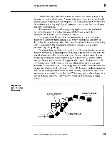
such as lane changes on the highway. Figure 8.24 illustrates the lane change for
front wheel steering and for this latter 4WS strategy, in which the same front
steering angle was used. Notice that the 4WS strategy yields a lane change in a
shorter distance and avoids the overshoot common in a standard-steering
vehicle.
Figure 8.24
Lane Change
Maneuver
FPO
UNDERSTANDING AUTOMOTIVE ELECTRONICS 293