
Page 311 - Understanding Automotive Electronics
P. 311
2735 | CH 9 Page 298 Tuesday, March 10, 1998 1:24 PM
9 AUTOMOTIVE INSTRUMENTATION
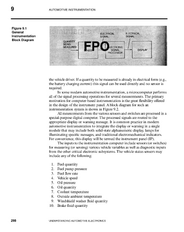
Figure 9.1
General
Instrumentation
Block Diagram
FPO
the vehicle driver. If a quantity to be measured is already in electrical form (e.g.,
the battery charging current) this signal can be used directly and no sensor is
required.
In some modern automotive instrumentation, a microcomputer performs
all of the signal processing operations for several measurements. The primary
motivation for computer-based instrumentation is the great flexibility offered
in the design of the instrument panel. A block diagram for such an
instrumentation system is shown in Figure 9.2.
All measurements from the various sensors and switches are processed in a
special-purpose digital computer. The processed signals are routed to the
appropriate display or warning message. It is common practice in modern
automotive instrumentation to integrate the display or warning in a single
module that may include both solid-state alphanumeric display, lamps for
illuminating specific messages, and traditional electromechanical indicators.
For convenience, this display will be termed the instrument panel (IP).
The inputs to the instrumentation computer include sensors (or switches)
for measuring (or sensing) various vehicle variables as well as diagnostic inputs
from the other critical electronic subsystems. The vehicle status sensors may
include any of the following:
1. Fuel quantity
2. Fuel pump pressure
3. Fuel flow rate
4. Vehicle speed
5. Oil pressure
6. Oil quantity
7. Coolant temperature
8. Outside ambient temperature
9. Windshield washer fluid quantity
10. Brake fluid quantity
298 UNDERSTANDING AUTOMOTIVE ELECTRONICS