
Page 315 - Understanding Automotive Electronics
P. 315
2735 | CH 9 Page 302 Tuesday, March 10, 1998 1:24 PM
9 AUTOMOTIVE INSTRUMENTATION
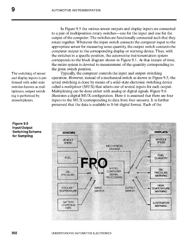
In Figure 9.5 the various sensor outputs and display inputs are connected
to a pair of multiposition rotary switches—one for the input and one for the
output of the computer. The switches are functionally connected such that they
rotate together. Whenever the input switch connects the computer input to the
appropriate sensor for measuring some quantity, the output switch connects the
computer output to the corresponding display or warning device. Thus, with
the switches in a specific position, the automotive instrumentation system
corresponds to the block diagram shown in Figure 9.1. At that instant of time,
the entire system is devoted to measurement of the quantity corresponding to
the given switch position.
The switching of sensor Typically, the computer controls the input and output switching
and display inputs is per- operation. However, instead of a mechanical switch as shown in Figure 9.5, the
formed with solid-state actual switching is done by means of a solid-state electronic switching device
switches known as mul- called a multiplexer (MUX) that selects one of several inputs for each output.
tiplexers; output switch- Multiplexing can be done either with analog or digital signals. Figure 9.6
ing is performed by illustrates a digital MUX configuration. Here it is assumed that there are four
demultiplexers. inputs to the MUX (corresponding to data from four sensors). It is further
presumed that the data is available in 8-bit digital format. Each of the
Figure 9.5
Input/Output
Switching Scheme
for Sampling
FPO
302 UNDERSTANDING AUTOMOTIVE ELECTRONICS