
Page 316 - Understanding Automotive Electronics
P. 316
2735 | CH 9 Page 303 Tuesday, March 10, 1998 1:24 PM
AUTOMOTIVE INSTRUMENTATION 9
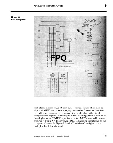
Figure 9.6
Data Multiplexer
FPO
multiplexers selects a single bit from each of the four inputs. There must be
eight such MUX circuits, each supplying one data bit. The output lines from
each MUX are connected to a corresponding data bus line in the digital
computer (see Chapter 4). Similarly, the output switching (which is often called
demultiplexing, or DEMUX) is performed with a MUX connected in reverse,
as shown in Figure 9.7. The MUX and DEMUX selection is controlled by the
computer. Note that in Figures 9.6 and 9.7, each bit of the digital code is
multiplexed and demultiplexed.
UNDERSTANDING AUTOMOTIVE ELECTRONICS 303