
Page 314 - Understanding Automotive Electronics
P. 314
2735 | CH 9 Page 301 Tuesday, March 10, 1998 1:24 PM
AUTOMOTIVE INSTRUMENTATION 9
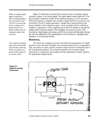
When an analog output Figure 9.4 illustrates a typical D/A converter used to transform digital
signal is required to computer output to an analog signal. The eight digital output leads (M = 8 in
drive an analog display, a this example) transfer the results of the signal processing to a D/A converter.
D/A converter is used. When the transfer is complete, the computer signals the D/A converter to start
The D/A converter gen- converting. The D/A output generates a voltage that is proportional to the
erates a voltage that is binary number in the computer output. A low, pass filter (which could be as
proportional to the simple as a capacitor) is often connected across the D/A output to smooth the
binary number that the analog output between samples. The sampling of the sensor output, A/D
computer sends to the conversion, digital signal processing, and D/A conversion all take place during
converter. the time slot allotted for the measurement of the variable in a sampling time
sequence, to be discussed shortly.
Multiplexing
The computer monitors Of course, the computer can only deal with the measurement of a single
each sensor individually quantity at any one time. Therefore, the computer input must be connected to
and provides output sig- only one sensor at a time, and the computer output must be connected only to
nals to its display com- the corresponding display. The computer performs any necessary signal
ponent before going on processing on a particular sensor signal and then generates an output signal to
to another sensor. the appropriate display device.
Figure 9.4
Digital-to-Analog
Conversion
FPO
UNDERSTANDING AUTOMOTIVE ELECTRONICS 301