
Page 333 - Understanding Automotive Electronics
P. 333
2735 | CH 9 Page 320 Tuesday, March 10, 1998 1:24 PM
9 AUTOMOTIVE INSTRUMENTATION
In the majority of applications (including TV), the electron beam is
scanned in a pattern known as a raster by means of specially located
electromagnets (see Figure 9.20). The magnetic fields created by the scanning
coils deflect the beam horizontally and vertically. The amount of deflection is
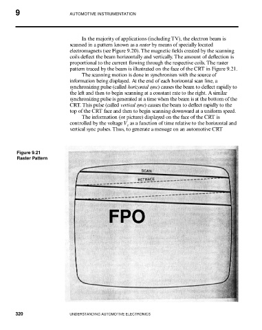
proportional to the current flowing through the respective coils. The raster
pattern traced by the beam is illustrated on the face of the CRT in Figure 9.21.
The scanning motion is done in synchronism with the source of
information being displayed. At the end of each horizontal scan line, a
synchronizing pulse (called horizontal sync) causes the beam to deflect rapidly to
the left and then to begin scanning at a constant rate to the right. A similar
synchronizing pulse is generated at a time when the beam is at the bottom of the
CRT. This pulse (called vertical sync) causes the beam to deflect rapidly to the
top of the CRT face and then to begin scanning downward at a uniform speed.
The information (or picture) displayed on the face of the CRT is
controlled by the voltage V as a function of time relative to the horizontal and
c
vertical sync pulses. Thus, to generate a message on an automotive CRT
Figure 9.21
Raster Pattern
FPO
320 UNDERSTANDING AUTOMOTIVE ELECTRONICS