
Page 335 - Understanding Automotive Electronics
P. 335
2735 | CH 9 Page 322 Tuesday, March 10, 1998 1:24 PM
9 AUTOMOTIVE INSTRUMENTATION
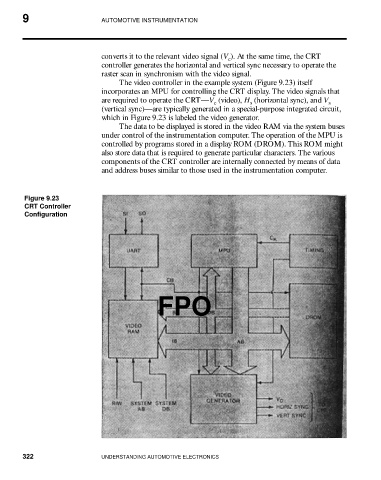
converts it to the relevant video signal (V ). At the same time, the CRT
c
controller generates the horizontal and vertical sync necessary to operate the
raster scan in synchronism with the video signal.
The video controller in the example system (Figure 9.23) itself
incorporates an MPU for controlling the CRT display. The video signals that
are required to operate the CRT—V (video), H (horizontal sync), and V
s
c
s
(vertical sync)—are typically generated in a special-purpose integrated circuit,
which in Figure 9.23 is labeled the video generator.
The data to be displayed is stored in the video RAM via the system buses
under control of the instrumentation computer. The operation of the MPU is
controlled by programs stored in a display ROM (DROM). This ROM might
also store data that is required to generate particular characters. The various
components of the CRT controller are internally connected by means of data
and address buses similar to those used in the instrumentation computer.
Figure 9.23
CRT Controller
Configuration
FPO
322 UNDERSTANDING AUTOMOTIVE ELECTRONICS