
Page 334 - Understanding Automotive Electronics
P. 334
2735 | CH 9 Page 321 Tuesday, March 10, 1998 1:24 PM
AUTOMOTIVE INSTRUMENTATION 9
display, a specific voltage pattern for V must be generated in timed relationship
c
to the sync pulses. This voltage is typically referred to as the video voltage.
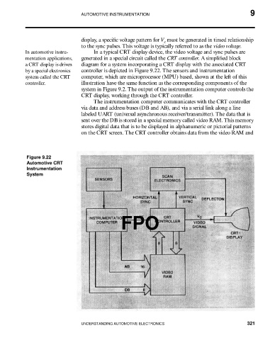
In automotive instru- In a typical CRT display device, the video voltage and sync pulses are
mentation applications, generated in a special circuit called the CRT controller. A simplified block
a CRT display is driven diagram for a system incorporating a CRT display with the associated CRT
by a special electronics controller is depicted in Figure 9.22. The sensors and instrumentation
system called the CRT computer, which are microprocessor (MPU) based, shown at the left of this
controller. illustration have the same function as the corresponding components of the
system in Figure 9.2. The output of the instrumentation computer controls the
CRT display, working through the CRT controller.
The instrumentation computer communicates with the CRT controller
via data and address buses (DB and AB), and via a serial link along a line
labeled UART (universal asynchronous receiver/transmitter). The data that is
sent over the DB is stored in a special memory called video RAM. This memory
stores digital data that is to be displayed in alphanumeric or pictorial patterns
on the CRT screen. The CRT controller obtains data from the video RAM and
Figure 9.22
Automotive CRT
Instrumentation
System
FPO
UNDERSTANDING AUTOMOTIVE ELECTRONICS 321