
Page 338 - Understanding Automotive Electronics
P. 338
2735 | CH 9 Page 325 Tuesday, March 10, 1998 1:24 PM
AUTOMOTIVE INSTRUMENTATION 9
variables and parameters that have traditionally been available to the driver, the
CRT can display engine data for diagnostic purposes (see Chapter 10), vehicle
comfort control system parameters, and entertainment system variables. The
data required for such displays can, for example, be transmitted via a high-
speed digital data (HSDD) link between the various on-board electronics
systems.
There are several reasons for using the serial HSDD link for transmitting
data between the various systems rather than tying the internal data buses
together. For example, it is desirable to protect any given system from a failure
in another. A defect affecting the data bus of the comfort system could
adversely affect the engine control system. In addition, each internal data bus
tends to be busy handling internal traffic. Moreover, the transfer of data to the
instrumentation computer can take place at relatively low data rates (for the
diagnostic application outlined here).
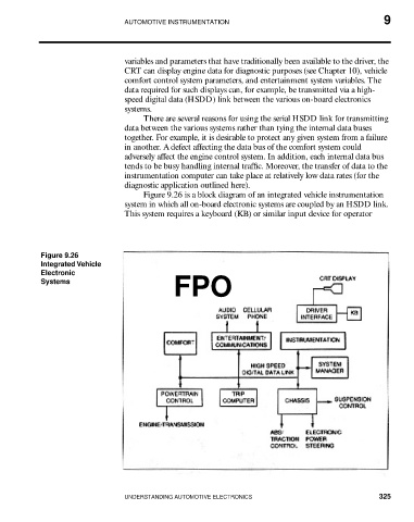
Figure 9.26 is a block diagram of an integrated vehicle instrumentation
system in which all on-board electronic systems are coupled by an HSDD link.
This system requires a keyboard (KB) or similar input device for operator
Figure 9.26
Integrated Vehicle
Electronic
FPO
Systems
UNDERSTANDING AUTOMOTIVE ELECTRONICS 325