
Page 92 - Understanding Automotive Electronics
P. 92
2735 | CH 3 Page 79 Tuesday, March 10, 1998 11:03 AM
ELECTRONICS FUNDAMENTALS 3
high input impedance is one of the primary features of the noninverting op
amp configuration.
A noninverting amplifier is also possible, as shown in Figure 3.4c. The
input signal is connected to the noninverting (+) terminal, and the output is
connected through a series connection of resistors to the inverting (–) input
terminal. The gain, A , in this case is
v
V out R f
A v = -------- = 1 + ----
V in R i
Besides adjusting gain, negative feedback also can help to correct for the
amplifier’s nonlinear operation and distortion.
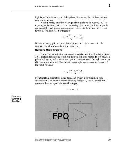
Summing Mode Amplifier
One of the important op amp applications is summing of voltages. Figure
3.5 is a schematic drawing of a summing mode op amp circuit. In this circuit, a
pair of voltages v and v (relative to ground) are connected through resistances
a b
R to the inverting input. The output voltage v is proportional to the sum of
o
the input voltages:
– R f V a + V b )
(
v o = ------------------------------
R
For example, a compatible stereo broadcast system incorporating a right
channel and a left channel characterized by voltages v and v , respectively,
R
L
transmits the sum v of the channel voltages:
S
v S = v R + v L
Figure 3.5
Summing
Amplifier
FPO
UNDERSTANDING AUTOMOTIVE ELECTRONICS 79