
Page 128 - Uninterruptible Power Supplies
P. 128
Harmonic Distortion of the Supply
126 Chapter Four
measurement is in use! Induction disc type integrating meters are
susceptible to error when connected to a severely distorted supply.
Power Factor Correction Capacitors
Any voltage distortion appearing across a power factor correction
capacitor will cause harmonic currents to flow. The currents will be pro-
portional to both the harmonic voltages and the harmonic numbers;
they can be large and can damage the capacitors, particularly if the
supply is being taken from a local generator.
Any lumped capacitance in the system may resonate at a harmonic
frequency with transformer leakage reactance. Resonance causes large
harmonic currents to flow in the components, and can lead to large har-
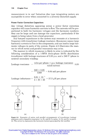
monic voltages in parts of the system. Figure 4.5 illustrates the man-
ner in which series and parallel resonances may arise.
The manner in which resonance is likely to arise is indicated by the
following consideration of a 1-MVA three-phase 50-Hz distribution
transformer with leakage reactance of 0.05 p.u. and a 240-V (phase to
neutral) secondary winding:
volts per phase p.u. leakage reactance
Leakage reactance (4.9)
rated current
240 0.05
8.64 m per phase
1389
8.64 10 3
Leakage inductance 27.5 H per phase
2
50
Figure 4.5 Examples of series and parallel arrangements of transformer leakage
reactance and a capacitive reactance. (a) X L and X C in series. (b) X L and X C in paral-
lel. The arrow I N represents the harmonic current generated by the rectifier.
Downloaded from Digital Engineering Library @ McGraw-Hill (www.digitalengineeringlibrary.com)
Copyright © 2004 The McGraw-Hill Companies. All rights reserved.
Any use is subject to the Terms of Use as given at the website.