
Page 132 - Uninterruptible Power Supplies
P. 132
Harmonic Distortion of the Supply
130 Chapter Four
The Effect of Harmonic Currents
The simplified Eq. 4.8 for estimating harmonic distortion of a supply
system indicates that the supply impedance determines the degree of
distortion. While this remains true for a supply derived from a genera-
tor, a generator is less amenable to analysis and only a brief descrip-
tion will be attempted here.
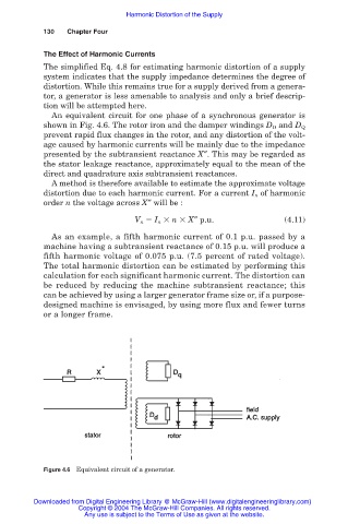
An equivalent circuit for one phase of a synchronous generator is
shown in Fig. 4.6. The rotor iron and the damper windings D D and D Q
prevent rapid flux changes in the rotor, and any distortion of the volt-
age caused by harmonic currents will be mainly due to the impedance
presented by the subtransient reactance X″. This may be regarded as
the stator leakage reactance, approximately equal to the mean of the
direct and quadrature axis subtransient reactances.
A method is therefore available to estimate the approximate voltage
distortion due to each harmonic current. For a current I n of harmonic
order n the voltage across X″ will be :
V n I n n X″ p.u. (4.11)
As an example, a fifth harmonic current of 0.1 p.u. passed by a
machine having a subtransient reactance of 0.15 p.u. will produce a
fifth harmonic voltage of 0.075 p.u. (7.5 percent of rated voltage).
The total harmonic distortion can be estimated by performing this
calculation for each significant harmonic current. The distortion can
be reduced by reducing the machine subtransient reactance; this
can be achieved by using a larger generator frame size or, if a purpose-
designed machine is envisaged, by using more flux and fewer turns
or a longer frame.
Figure 4.6 Equivalent circuit of a generator.
Downloaded from Digital Engineering Library @ McGraw-Hill (www.digitalengineeringlibrary.com)
Copyright © 2004 The McGraw-Hill Companies. All rights reserved.
Any use is subject to the Terms of Use as given at the website.