
Page 134 - Uninterruptible Power Supplies
P. 134
Harmonic Distortion of the Supply
132 Chapter Four
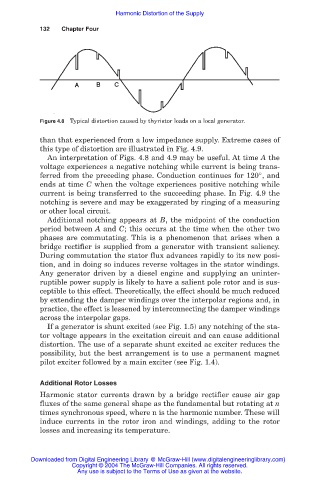
Figure 4.8 Typical distortion caused by thyristor loads on a local generator.
than that experienced from a low impedance supply. Extreme cases of
this type of distortion are illustrated in Fig. 4.9.
An interpretation of Figs. 4.8 and 4.9 may be useful. At time A the
voltage experiences a negative notching while current is being trans-
ferred from the preceding phase. Conduction continues for 120°, and
ends at time C when the voltage experiences positive notching while
current is being transferred to the succeeding phase. In Fig. 4.9 the
notching is severe and may be exaggerated by ringing of a measuring
or other local circuit.
Additional notching appears at B, the midpoint of the conduction
period between A and C; this occurs at the time when the other two
phases are commutating. This is a phenomenon that arises when a
bridge rectifier is supplied from a generator with transient saliency.
During commutation the stator flux advances rapidly to its new posi-
tion, and in doing so induces reverse voltages in the stator windings.
Any generator driven by a diesel engine and supplying an uninter-
ruptible power supply is likely to have a salient pole rotor and is sus-
ceptible to this effect. Theoretically, the effect should be much reduced
by extending the damper windings over the interpolar regions and, in
practice, the effect is lessened by interconnecting the damper windings
across the interpolar gaps.
If a generator is shunt excited (see Fig. 1.5) any notching of the sta-
tor voltage appears in the excitation circuit and can cause additional
distortion. The use of a separate shunt excited ac exciter reduces the
possibility, but the best arrangement is to use a permanent magnet
pilot exciter followed by a main exciter (see Fig. 1.4).
Additional Rotor Losses
Harmonic stator currents drawn by a bridge rectifier cause air gap
fluxes of the same general shape as the fundamental but rotating at n
times synchronous speed, where n is the harmonic number. These will
induce currents in the rotor iron and windings, adding to the rotor
losses and increasing its temperature.
Downloaded from Digital Engineering Library @ McGraw-Hill (www.digitalengineeringlibrary.com)
Copyright © 2004 The McGraw-Hill Companies. All rights reserved.
Any use is subject to the Terms of Use as given at the website.