
Page 54 - Uninterruptible Power Supplies
P. 54
Interconnecting the Standby and Normal Supplies
52 Chapter Two
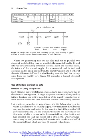
Figure 2.3 Single-line diagram and switching status table showing a typical
method of connecting two sets with two stages of load shedding.
Where two generating sets are installed and run in parallel, two
stages of load shedding may be provided; the essential load is divided
into two parts which may be termed essential load 1 and essential load 2.
On failure of the normal supply, the nonessential load is shed and
essential loads 1 and 2 are fed from the standby supply, and if either of
the sets fails essential load 2 is shed leaving essential load 1 to be sup-
plied from the healthy set. Figure 2.3 indicates a typical electrical
arrangement.
Use of Multiple Generating Sets
Reasons for Using Multiple Sets
Most standby power installations use a single generating set; this is
the simplest arrangement. A single set provides no redundancy and its
failure deprives the entire installation of its standby supply; two or
more sets are sometimes used for one or more of the following reasons:
■ A single set provides no redundancy and its failure deprives the
entire installation of its standby supply. Very important installations
may use two sets, each rated for the essential load, this provides 100
percent redundancy. On loss of supply both sets are started and the
first set available is connected to the essential load; after the first set
has accepted the load the second set is shut down. Other arrange-
ments may be used, for example three sets each rated for one half of
the essential load, which provides 50 percent redundancy.
Downloaded from Digital Engineering Library @ McGraw-Hill (www.digitalengineeringlibrary.com)
Copyright © 2004 The McGraw-Hill Companies. All rights reserved.
Any use is subject to the Terms of Use as given at the website.