
Page 95 - Uninterruptible Power Supplies
P. 95
Additional Information Relating to the Standby Supply Installation
Additional Information Relating to the Standby Supply Installation 93
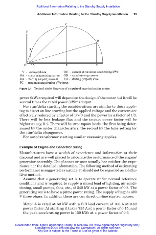
Figure 3.1 Typical circle diagram of a squirrel cage induction motor.
power (kWe) required will depend on the design of the motor but it will be
several times the rated power (kWm) output.
For star/delta starting the considerations are similar to those apply-
ing to direct on line starting but the applied voltage and the current are
effectively reduced by a factor of 1/ 3 and the power by a factor of 1/3.
There will be less leakage flux and the impact power factor will be
higher at say, 0.4. There will be two impact loads, the first being deter-
mined by the motor characteristics, the second by the time setting for
the star/delta changeover.
For auto/transformer starting similar reasoning applies.
Example of Engine and Generator Sizing
Manufacturers have a wealth of experience and information at their
disposal and are well placed to calculate the performance of the engine/
generator assembly. The planner or user usually has neither the expe-
rience nor the detailed information. The following method of estimating
performance is suggested as a guide, it should not be regarded as a defin-
itive method.
Assume that a generating set is to operate under normal reference
conditions and is required to supply a mixed load of lighting, air condi-
tioning, small pumps, fans, etc., of 240 kW at a power factor of 0.8. The
generating set is to have a prime power rating. The supply voltage is 400
V three phase. In addition there are two direct on-line started motors:
Motor A is rated at 60 kW with a full load current of 105 A at 0.89
power factor. At starting it takes 735 A at a power factor of 0.15, and
the peak accelerating power is 150 kWe at a power factor of 0.6.
Downloaded from Digital Engineering Library @ McGraw-Hill (www.digitalengineeringlibrary.com)
Copyright © 2004 The McGraw-Hill Companies. All rights reserved.
Any use is subject to the Terms of Use as given at the website.