
Page 97 - Uninterruptible Power Supplies
P. 97
Additional Information Relating to the Standby Supply Installation
Additional Information Relating to the Standby Supply Installation 95
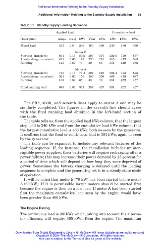
TABLE 3.1 Standby Supply Loading Sequence
Applied load Cumulative load
Description Amps. cos kWe kVAr kVA kWe kVAr kVA
Mixed load 433 0.8 240 180 300 240 180 300
Motor B
Starting (transient) 861 0.15 89.5 590 597 329.5 770 837
Accelerating (transient) 421 0.60 175 233 291 415 413 585
Running 123 0.89 76 39 85 316 219 385
Motor A
Starting (transient) 735 0.15 76.4 504 510 392.4 723 823
Accelerating (transient) 361 0.60 150 200 250 466 419 627
Running 105 0.89 65 33 73 381 252 457
Final running load 660 0.83 381 252 457 381 252 457
The fifth, sixth, and seventh lines apply to motor A and may be
similarly completed. The figures in the seventh line should agree
with the final running load obtained in the left-hand section of
the table.
The table tells us, from the applied load kWe column, that the largest
step load is 240 kWe and from the cumulative load kWe column, that
the largest cumulative load is 466 kWe, both as seen by the generator.
It confirms that the final or continuous load is 381 kWe, again as seen
by the generator.
The table can be expanded to include any relevant features of the
loading sequence. If, for instance, the installation includes uninter-
ruptible power supplies, their batteries will require recharging after a
power failure; this may increase their power demand by 25 percent for
a period of time which will depend on how long they were deprived of
power. Sometimes the battery charging is delayed until the loading
sequence is complete and the generating set is in a steady-state mode
of operation.
It will be noted that motor B (70 kW) has been started before motor
A (60 kW). If it is permissible larger motors should be started first
because the engine is then on a low load. If motor A had been started
first the maximum cumulative load seen by the engine would have
been greater than 466 kWe.
The Engine Rating
The continuous load is 381kWe which, taking into account the alterna-
tor efficiency, will require 405 kWm from the engine. The maximum
Downloaded from Digital Engineering Library @ McGraw-Hill (www.digitalengineeringlibrary.com)
Copyright © 2004 The McGraw-Hill Companies. All rights reserved.
Any use is subject to the Terms of Use as given at the website.