
Page 200 - Urban Construction Project Management
P. 200
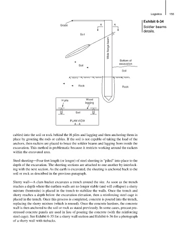
Logistics  155
                                                                                   Exhibit 6-34
                                    Grade                 A       A
                                                                                   Soldier beams
                                                                                   details.
                                               Soil
                                                               Wide flange beam


                                                                     Bottom of
                                                                     excavation
                                              Soil
                                                                        Soil


                                               Rock
                                                                        Rock


                                     H pile        Wood
                                                  lagging

                                             Soil

                                          PLAN VIEW
                                            A - A


          cables) into the soil or rock behind the H piles and lagging and then anchoring them in
          place by grouting the rods or cables. If the soil is not capable of taking the load of the
          anchors, then rackers are placed to brace the soldier beams and lagging from inside the
          excavation. This method is problematic because it restricts working around the rackers
          within the excavated area.

          Steel sheeting—Four feet length (or longer) of steel sheeting is “piled” into place to the
          depth of the excavation. The sheeting sections are attached to one another by interlock-
          ing with the next section. As the earth is excavated, the sheeting is anchored back to the
          soil or rock as described in the previous paragraph.


          Slurry wall—A clam bucket excavates a trench around the site. As soon as the trench
          reaches a depth where the earthen walls are no longer stable (and will collapse) a slurry
          mixture (bentonite) is placed in the trench to stabilize the walls. Once the trench and
          slurry reaches a depth below the excavation elevation, then a reinforcing steel cage is
          placed in the trench. Once this process is completed, concrete is poured into the trench,
          replacing the slurry mixture (which is reused). Once the concrete hardens, the concrete
          wall is then anchored to the soil or rock as stated previously. In some cases, precast pre-
          stressed concrete panels are used in lieu of pouring the concrete (with the reinforcing
          steel cage). See Exhibit 6-35 for a slurry wall section and Exhibit 6-36 for a photograph
          of a slurry wall with tiebacks.