
Page 123 - Using ANSYS for Finite Element Analysis A Tutorial for Engineers
P. 123
110 • Using ansys for finite element analysis
Are these results what you expected? Note that all the DOFs were
constrained to zero at node 1, while UY was constrained to zero at node 7.
If you wanted to save these results to a file, select File within the
results window (at the upper left-hand corner of this list window) and
select Save as.
19. Axial stress:
For line elements (i.e., links, beams, spars, and pipes), you will
often need to use the Element Table to gain access to derived data (i.e.,
stresses, strains). For this, example we should obtain axial stress to com-
pare with the hand calculations. The Element Table is different for each
element; therefore, we need to look at the help file for LINK1 (Type help
link1 into the Input Line). From Table 1.2 in the Help file, we can see that
SAXL can be obtained through the ETABLE, using the item LS,1.
From the General Postprocessor menu, select:
Element Table > Define Table
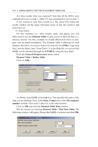
Click on Add....
As shown, enter SAXL in the Lab box. This specifies the name of the
item you are defining. Next, in the Item, Comp boxes, select By sequence
number and LS. Then enter 1 after LS, in the selection box.
Click on OK and close the Element Table Data window.
Plot the stresses by selecting Element Table > Plot Elem Table. The
following window will appear. Ensure that SAXL is selected and click OK.