
Page 19 - Using ANSYS for Finite Element Analysis A Tutorial for Engineers
P. 19
6 • Using ansys for finite element analysis
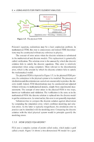
Mathematical
model
Solution
Physical Complicated model Discrete
problem solution
Verification
solution error
Simulation error = Modeling + Solution error
Figure 1.5. The physical FEM.
Poisson’s equation, realizations may be a heat conduction problem. In
mathematical FEM, this step is unnecessary and indeed FEM discretiza-
tions may be constructed without any reference to physics.
The concept of error arises when the discrete solution is substituted
in the mathematical and discrete models. This replacement is generically
called verification. The solution error is the amount by which the discrete
solution fails to satisfy the discrete equations. This error is relatively
unimportant when using computers. More relevant is the discretization
error, which is the amount by which the discrete solution fails to satisfy
the mathematical model.
The physical FEM is depicted in Figure 1.5; in the physical FEM pro-
cess, the centerpiece is the physical system to be modeled. The processes of
idealization and discretization are carried out concurrently to produce the dis-
crete model. Indeed, FEM discretizations may be constructed and adjusted
without reference to mathematical models, simply from experimental mea-
surements. The concept of error arises in the physical FEM in two ways,
known as verification and validation. The verification is the same as in the
mathematical FEM: the discrete solution is replaced into the discrete model
to get the solution error. As noted earlier, this error is not generally important.
Validation tries to compare the discrete solution against observation
by computing the simulation error, which combines modeling and solu-
tion errors. As the latter is typically insignificant, the simulation error in
practice can be identified with the modeling error. Comparing the discrete
solution with the ideal physical system would in principle quantify the
modeling errors.
1.1.5 how does fea work?
FEA uses a complex system of points called nodes, which make a grid
called a mesh. Figure 1.6 shows a two-dimensional FE model for a gear