
Page 20 - Using ANSYS for Finite Element Analysis A Tutorial for Engineers
P. 20
IntroductIon to FInIte element AnAlysIs • 7
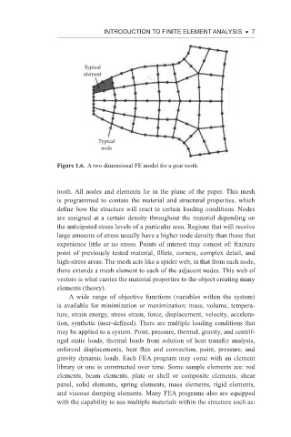
Typical
element
Typical
node
Figure 1.6. A two dimensional FE model for a gear tooth.
tooth. All nodes and elements lie in the plane of the paper. This mesh
is programmed to contain the material and structural properties, which
define how the structure will react to certain loading conditions. Nodes
are assigned at a certain density throughout the material depending on
the anticipated stress levels of a particular area. Regions that will receive
large amounts of stress usually have a higher node density than those that
experience little or no stress. Points of interest may consist of: fracture
point of previously tested material, fillets, corners, complex detail, and
high-stress areas. The mesh acts like a spider web, in that from each node,
there extends a mesh element to each of the adjacent nodes. This web of
vectors is what carries the material properties to the object creating many
elements (theory).
A wide range of objective functions (variables within the system)
is available for minimization or maximization: mass, volume, tempera-
ture, strain energy, stress strain, force, displacement, velocity, accelera-
tion, synthetic (user-defined). There are multiple loading conditions that
may be applied to a system. Point, pressure, thermal, gravity, and centrif-
ugal static loads, thermal loads from solution of heat transfer analysis,
enforced displacements, heat flux and convection, point, pressure, and
gravity dynamic loads. Each FEA program may come with an element
library or one is constructed over time. Some sample elements are: rod
elements, beam elements, plate or shell or composite elements, shear
panel, solid elements, spring elements, mass elements, rigid elements,
and viscous damping elements. Many FEA programs also are equipped
with the capability to use multiple materials within the structure such as: