
Page 226 - Materials Chemistry, Second Edition
P. 226
CAT3525_C07.qxd 1/29/2005 9:57 AM Page 197
Municipal Solid Waste Processing; Materials Recovery Facilities 197
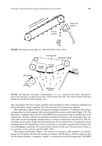
FIGURE 7.26 Magnetic head pulley (U.S. EPA, EPA/625/6-91/031, 1991).
FIGURE 7.27 Magnetic belt pulley. (Tchobanoglous, G., et al., Integrated Solid Waste Management:
Engineering Principles and Management Issues. McGraw-Hill, New York, 1993. Data reproduced with kind
permission of the McGraw-Hill Companies, Inc.)
and is discharged. The drum magnet assembly can be installed for either overfeed or underfeed and
directs the ferrous along a trajectory other than that taken by the nonferrous material.
The single-drum magnet tends to entrap pieces of paper and plastics. To minimize this problem
a design using two-drum magnets with an intermediate belt conveyor can be used (Figure 7.28). The
first drum is suspended above the end of the MSW feed conveyor and rotates in the direction of the
material flow. Ferrous materials are picked up and directed forward to the intermediate belt con-
veyor. Most of the nonmagnetic materials fall to a conveyor located below the first drum. The sec-
ond drum, which can be smaller than the first because of less material flow, is positioned over the
discharge end of the intermediate conveyor, and rotates in a direction opposite to the material flow
to avoid bridging or jamming. The ferrous metal is carried over the top of the drum and released on
to a conveyor or bin on the far end (U.S. EPA, 1991).
The magnetic head pulley (Figure 7.26) conveyor is arranged so that material to be sorted is
passed over the pulley such that the nonferrous material will fall along a different trajectory than
will the ferrous material. A separator (‘splitter’) is positioned over the discharge end of the MSW