
Page 230 - Materials Chemistry, Second Edition
P. 230
CAT3525_C07.qxd 1/29/2005 9:57 AM Page 201
Municipal Solid Waste Processing; Materials Recovery Facilities 201
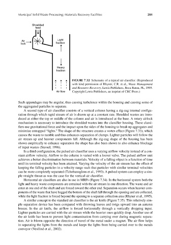
FIGURE 7.32 Schematic of a typical air classifier. (Reproduced
with kind permission of Rhyner, C.R. et al., Waste Management
and Resource Recovery, Lewis Publishers, Boca Raton, FL, 1995.
Copyright Lewis Publishers, an imprint of CRC Press.)
Such appendages may be angular, thus causing turbulence within the housing and causing some of
the aggregated particles to separate.
A second type of air classifier consists of a vertical column having a zig-zag internal configu-
ration through which rapid stream of air is drawn up at a constant rate. Shredded wastes are intro-
duced at either the top or middle of the column and air is introduced at the base. A rotary airlock
mechanism is necessary to introduce the shredded wastes into the classifier housing. These classi-
fiers use gravitational force and the impact upon the sides of the housing to break up aggregates and
minimize entrapped “lights.” The shape of the structure creates a vortex effect (Figure 7.33), which
causes the waste to tumble and thus enhances separation of clumps. Lighter particles will follow the
air stream up and heavier components fall. Although the zig-zag shape of the housing has been
shown empirically to enhance separation the shape has also been shown to also enhance blockage
of input wastes (Stessel, 1996).
In a third configuration, the pulsed air classifier uses a varying airflow velocity instead of a con-
stant airflow velocity. Airflow to the column is varied with a louver valve. The pulsed airflow unit
achieves a better discrimination between materials. Velocity of a falling object is a function of time
until its terminal velocity has been attained. Varying the velocity of the air stream has the effect of
keeping the falling particles in a velocity range such that particles with similar terminal velocities
can be more completely separated (Tchobanoglous et al., 1993). A pulsed system can employ a sim-
ple straight throat as was the case for the vertical air classifier.
Horizontal air classifiers are also in use in MRFs (Figure 7.34). In the horizontal system both the
light and heavy waste components are entrained with the air stream in one direction. The waste and air
enter at one end of the shaft and are forced toward the other end. Separation occurs when heavier com-
ponents of the waste that have hugged the bottom of the shaft fall through the opening and are collected,
while the light fraction is forced beyond the opening to a separate collection area (Rhyner et al., 1995).
A similar concept to the standard air classifier is the air knife (Figure 7.35). This relatively sim-
ple separation device has been compared with throwing leaves and twigs upward into an autumn
breeze. In the air knife, the airflow is forced horizontally through a vertically dropping input.
Lighter particles are carried with the air stream while the heavier ones quickly drop. Another use of
the air knife has been to prevent light contamination from carrying over during magnetic separa-
tion. Air is blown opposite the direction of travel of the metal under a magnet. The air flow helps
in separating the lights from the metals and keeps the lights from being carried over to the metals
conveyor (Vesilind et al., 2002).