
Page 364 - Materials Chemistry, Second Edition
P. 364
CAT3525_C10.qxd 1/31/2005 12:00 PM Page 335
The Sanitary Landfill 335
operation, leachate passes through the area collector, into collection laterals, and drains to a sump
where it is removed from the landfill.
A number of materials are appropriate for the manufacture of leachate collection systems.
Polymeric pipes are by far the most common. HDPE and PVC are used almost exclusively and are
available as either profiled or smooth wall construction (Qian et al., 2002).
The design of perforated leachate collection pipes must address the following issues (Qian et
al., 2002):
● The required flow
● Maximum drainage slope
● Maximum pipe spacing
● Pipe size
● Structural strength of the pipe
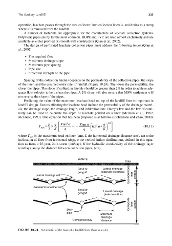
Spacing of the collection laterals depends on the permeability of the collection pipes, the slope
of the liner, and the assumed entry rate of rainfall (Figure 10.24). The lower the permeability, the
closer the pipes. The slope of collection laterals should be greater than 2% in order to achieve ade-
quate flow velocity to help clean the pipes. A 2% slope will also ensure that MSW settlement will
not reverse the slope of the pipes.
Predicting the value of the maximum leachate head on top of the landfill liner is important in
landfill design. Factors affecting the leachate head include the permeability of the drainage materi-
als, the drainage slope, the drainage length, and infiltration rate. Darcy’s law and the law of conti-
nuity can be used to calculate the depth of leachate ponded on a liner (McBean et al., 1982;
McEnroe, 1993). One equation that has been proposed is as follows (Richardson and Zhao, 2000):
2
p q Ktan α Ktan α q 1/2
2
Y max 1 tan α (10.11)
2 K q q K
where Y is the maximum head on liner (cm), L the horizontal drainage distance (cm), tan α the
max
inclination of liner from horizontal (deg), q the vertical inflow (infiltration), defined in this equa-
tion as from a 25-year, 24-h storm (cm/day), K the hydraulic conductivity of the drainage layer
(cm/day), and p the distance between collection pipes, (cm).
WASTE
Filter
Geomembrane liner system
Sand or Lateral drainage
geogrid (leachate detection)
Lateral drainage net
Geomembrane liner
Sand or Lateral drainage
geogrid
(leak detection)
Composite liner system
Drain
pipe Maximum
drainage
Compacted clay distance
FIGURE 10.24 Schematic of the base of a landfill liner (Not to scale).