
Page 368 - Materials Chemistry, Second Edition
P. 368
CAT3525_C10.qxd 1/31/2005 12:00 PM Page 339
The Sanitary Landfill 339
Written closure plans must describe all steps necessary to close landfill units. After closure of a unit,
postclosure care is required for at least 30 years. The following issues must be addressed at a minimum:
● Maintain the integrity and effectiveness of the final cover
● Maintain and operate the leachate collection system in accordance with 40 CFR 258.40
● Monitor groundwater in accordance with 40 CFR 258 and maintain the groundwater-
monitoring system
● Maintain and operate the gas-monitoring system in accordance with 40 CFR 258.23
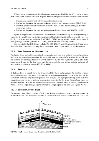
Figure 10.28 provides a schematic of a recommended top slope cap. By restricting the entry of
water into the landfill by a cap system, generation of leachate is substantially minimized. However,
the dry conditions that are maintained will hinder MSW biodegradation, making most landfills
merely storage facilities (Vesilind et al., 2002), sometimes known as ‘dry tombs.’
Components for landfill closure include (40 CFR 258.60) an infiltration (barrier) layer or an
alternative barrier system, a drainage layer, an erosion control layer, and a gas venting system.
10.5.1 LOW PERMEABILITY (BARRIER) LAYER
The barrier layer for landfills consists of a compacted soil layer or a soil and geomembrane liner.
Both systems are designed to reduce the rate at which surface water infiltrates into the landfill unit.
An alternative barrier system may be used if approved by the state regulatory agency. The mem-
brane material used for the final cover must be composed of a long-lasting material and must tol-
erate subsidence-induced strains (U.S. EPA, 1994).
10.5.2 DRAINAGE LAYER
A drainage layer is placed above the low-permeability layer and maintains the stability of cover
slopes by eliminating pore water. A drainage layer in the cover system is not required under RCRA
Subtitle D; however, large landfills possess such a layer. This layer prevents any water that infil-
trates the erosion control layer from accumulating above the barrier layer. Accumulated water can
generate pressure above the membrane and cause the erosion control layer to slide off the cover side
slopes. The side slope drainage layer is drained to a large capacity toe drain (see Figure 10.19).
10.5.3 EROSION CONTROL LAYER
The erosion control layer consists of soil planted with vegetation to protect the cover from the
effects of erosion. The minimum thickness of the erosion layer required under Subtitle D is 15 cm
Gas vent
Top layer
Geomembrane Drain layer
Low-permeability
Perforated Geomembrane/soil layer
Vent layer
pipe
Waste
FIGURE 10.28 Cover design for a closed landfill (U.S. EPA, 1994).