
Page 199 - Water Engineering Hydraulics, Distribution and Treatment
P. 199
5. At a distance within 20% of the orifice diameter upstream
4. Total energy:
Entering = 44 ft = 13.4112 m.
Determine the coefficients of velocity, discharge, and con-
Leaving = 179 ft = 55.5592 m.
traction for a jet of liquid flow through an orifice. Assume the actual
velocity in the contracted section of the liquid jet flowing from a
Determine the pressure increase in psi (kN/m ) between enter-
2-in. (50.8-mm)-diameter orifice is 30 ft/s (9.144 m/s), under a head
ing and leaving liquid streams.
3
3
of 16 ft (4.877 m). Actual flow is 0.4 ft /s (0.0113 m /s).
5.34
Consider the parallel pipe system in Fig. 5.47. The following
5.39
A flat plate, 4 ft by 4 ft (1.22 m by 1.22 m), moves at
data are known:
23 ft/s (7.01 m/s) normal to its plane at standard pressure. Deter-
Pipe c is a 10 in. (254 mm) water line.
mine the resistance of the plate assuming the drag coefficient =
Pipe d is a 12 in. (304.8 mm) water main. 2 5.38 from the plane of the orifice Problems/Questions 177 3
1.16 for length/width ratio equal to 1 and = 0.0752 lb/ft
Pipe a is a 6 in. (152.4 mm) line, 1,000 ft (304.8 m) long. 3 air
(0.01181 kN/m ).
Pipe b is a 6 in. (152.4 mm) line, 1,440 ft (438.9 m) long.
Water velocity in pipe b is 10 ft/s (3.048 m/s).
Friction factors in the two pipes a and b are the same and the 5.40 A standard orifice discharges under a head H as shown in
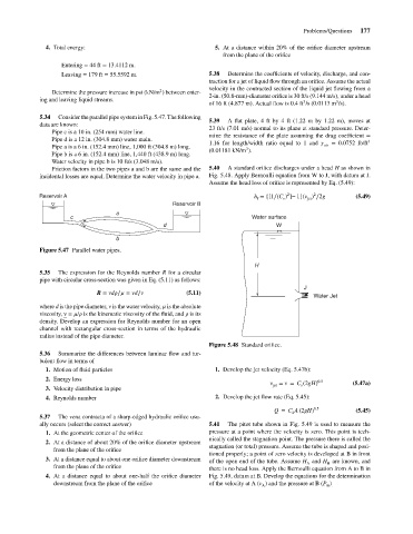
incidental losses are equal. Determine the water velocity in pipe a. Fig. 5.48. Apply Bernoulli equation from W to J, with datum at J.
Assume the head loss of orifice is represented by Eq. (5.49):
2
2
Reservoir A h = {[1∕(C ) ]− 1}(v ) ∕2g (5.49)
v
f
jet
Reservoir B
a
c Water surface
d W
b
Figure 5.47 Parallel water pipes.
H
5.35 The expression for the Reynolds number R for a circular
pipe with circular cross-section was given in Eq. (5.11) as follows:
J
R = vd ∕ = vd∕v (5.11)
Water Jet
where d is the pipe diameter, v is the water velocity, is the absolute
viscosity, v = / is the kinematic viscosity of the fluid, and is its
density. Develop an expression for Reynolds number for an open
channel with rectangular cross-section in terms of the hydraulic
radius instead of the pipe diameter.
Figure 5.48 Standard orifice.
5.36 Summarize the differences between laminar flow and tur-
bulent flow in terms of
1. Motion of fluid particles 1. Develop the jet velocity (Eq. 5.47b):
2. Energy loss
v = v = C (2gH) 0.5 (5.47a)
3. Velocity distribution in pipe jet v
4. Reynolds number 2. Develop the jet flow rate (Eq. 5.45):
Q = C A (2gH) 0.5 (5.45)
d
5.37 The vena contracta of a sharp-edged hydraulic orifice usu-
ally occurs (select the correct answer) 5.41 The pitot tube shown in Fig. 5.49 is used to measure the
1. At the geometric center of the orifice pressure at a point where the velocity is zero. This point is tech-
nically called the stagnation point. The pressure there is called the
2. At a distance of about 20% of the orifice diameter upstream
stagnation (or total) pressure. Assume the tube is shaped and posi-
from the plane of the orifice
tioned properly; a point of zero velocity is developed at B in front
3. At a distance equal to about one orifice diameter downstream of the open end of the tube. Assume H and H are known, and
A
B
from the plane of the orifice there is no head loss. Apply the Bernoulli equation from A to B in
4. At a distance equal to about one-half the orifice diameter Fig. 5.49, datum at B. Develop the equations for the determination
downstream from the plane of the orifice of the velocity at A (v ) and the pressure at B (P )
A
B .