
Page 200 - Water Engineering Hydraulics, Distribution and Treatment
P. 200
178
Water Hydraulics, Transmission, and Appurtenances
Chapter 5
2
the pressure is 35 psig (242.9 kPa = 242.9 kN/m ). At point B
5,000 ft (1,524 m) downstream of the pipe, the elevation is 135 ft
2
(41.148 m) and the pressure is 40 psig (277.6 kPa = 277.6 kN/m ).
Determine the head loss between points A and B.
A 24 in. (609.6 mm), 5,000 ft (1524 m) pipeline carries
5.48
H A
3
1.6 ft /s (0.453 m /s) of water between points A and B. The head
loss between A and B is 8.46 ft (2.56 m). Determine the velocity of
flow and the pipe friction factor f.
5.49
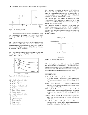
A water jet shown in Fig. 5.51 flows vertically upward from
A
a nozzle with a vertical velocity of 16 ft/s (4.8768 m/s) and a flow
3
3
rate of 0.03 ft /s (0.0008496 m /s). Above the nozzle at a distance
Figure 5.49 Standard pitot tube. B H B 5.47 3 At point A in a pipeline, the elevation is 155 ft (47.244 m);
h = 6 in. (152.4 mm), there is a horizontal plate weighing 0.5 lb
(0.227 kg). Determine the reaction force F which is required to hold
5.42 Determine the flow from a standard orifice J shown in Fig. the plate stationary.
5.48. The head above the orifice H = 20 ft (6.096 m), the orifice
diameter equals 4.5 in. (114.3 mm), and discharge coefficient C = Reaction force
d
0.594. F
Horizontal plate
5.43 The pitot tube shown in Fig. 5.49 has a coefficient of 0.9850.
It is used to measure the velocity of water at the center of a pipe.
Assume a stagnation pressure head H of 19 ft (5.7912 m) and the
B
static pressure head H in the pipe of 16 ft (4.8768 m). Determine h
A
the velocity at A and the pressure at B.
5.44 Given an over-simplified Moody diagram (Fig. 5.50) and V, Q Nozzle
the original Moody diagram (Fig. 5.11), explain the applications of
curves A, B, C, D, and E.
Center line
Figure 5.51 Water jet from a nozzle.
E
5.50 A rectangular wood block floats in water with 6.2 in. (157.48
D mm) projecting above the water surface. If the same wood block
f
is placed in an organic solvent of specific gravity 0.81, the wood
C block projects 4.2 in. (106.68 mm) above the surface of the organic
A solvent. Determine the specific gravity of the wood block.
B
2,000 R
REFERENCES
Figure 5.50 Simplified Moody diagram.
Al-Dhowalia, K. and Shammas, N. K., Leak detection and quan-
tification of losses in a water network, International Journal
5.45 Briefly and precisely define of Water Resources Development, vol. 7, no. 1, pp. 30–38,
1. The Moody diagram 1991.
2. The Bernoulli equation Bradley, J. N. and Thompson, L. R., Friction factors for large con-
duits flowing full, Bureau of Reclamation Engineering Mono-
3. The Darcy–Weisbach formula
graph 7, Denver, CO, 1951.
4. The Chezy formula
Colebrook, C. F., Turbulent flow in pipes, with particular ref-
5. Hazen–Williams formula erence to the transition region between the smooth and
6. Manning equation rough pipe laws, Journal of the ICE, vol. 11, pp. 133–156,
5.46 Briefly and precisely define 1939.
1. Pitot tube Colebrook, C. F. and White, C. M., The reduction of carrying capac-
ity of pipes with age, Journal of the ICE, vol. 7, pp. 99–118,
2. Stagnation pressure
1937–1938.
3. Hydraulic gradient
Fair, G. M., Geyer, J. C., and Okun, D. A., Water and Wastewater
4. Energy gradient Engineering, vol. 1: Water Supply and Wastewater Removal,
5. Friction head loss John Wiley & Sons, Inc., New York, 1966.