Page 221 - Water Engineering Hydraulics, Distribution and Treatment
P. 221

Gate N
                                                              Gauge B
                                                      Gate M
                                                                                               To private
                                    From public
                                                           3
                                                           / 4 ˝ test
                                                                                                system
                                    water main
                                                 Gauge A
                                                           drain D
                                                                            3
                                                                            / 4 ˝ test drain E
                                                                                Check valve G
                                                   Check valve F
                                                                           Steel foothold inserts
                                                  Brick or concrete pit
                                                                    Plan Gauge C 6.8 Management, Operation, and Maintenance of Distribution Systems  199
                                                                             Indicator post
                                                                                 optional
                                                                   Manhole
                                                       Wood cover
                                                                             Steel foothold
                                                                             inserts
                                                         Gauge A
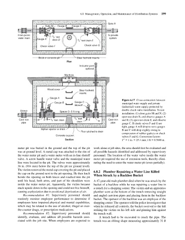
                                                                                                         Figure 6.17 Cross-connection between
                                                            Gauge B      Gauge C                         municipal water supply and private
                                                                          Blowoff
                                                                                                         (industrial) water supply protected by
                                      Sleeve                    Spacer 3–5 ft long                       double check-valve installation. To test
                                                        F                         G                      installation: (1) close gates M and N; (2)
                                                                                                         open test drain B, and observe gauges A
                                                                         3 / 4 ˝ test
                                     Cast-iron   M   D    3 / 4 ˝ test drain       E     N      Cast-iron  and B; (3) open test drain E, and observe
                                      pipe                                 drain                  pipe   gauge C. If check valves F and G are
                                                                                                         tight, gauge A will drop to zero; gauges
                                                   Siphon ejector or drain                               B and C will drop slightly owing to
                                                                              Floor pitched to drain
                                                                                                         compression of rubber gaskets on check
                                                             Concrete support
                                                                                                         valves F and G. Conversion factors:
                                                                   Section                               1 = 1in. = 25.4 mm; 1 ft = 0.3048 m.
                                                                                                          ′′
                                    meter pit was buried in the ground and the top of the pit  work alone at job sites, the area should first be evaluated and
                                    was at ground level. A metal cap was attached to the rim of  all possible hazards identified and addressed by supervisory
                                    the water meter pit and a water meter with an in-line shutoff  personnel. The location of the water valve inside the water
                                    valve. A screw handle water valve and the municipal water  meter pit required the use of extension tools, thereby elimi-
                                    line were located in the pit. The valves were approximately  nating the need to enter the water meter pit (even partially).
                                    36 in. (914 mm) below the top of the pit (or ground level).
                                    The victim removed the metal cap covering the pit and placed
                                                                                      6.8.2 Plumber Repairing a Water Line Killed
                                    the cap on the ground next to the pit opening. He then knelt
                                                                                      When Struck by a Backhoe Bucket
                                    beside the opening on both knees and reached into the pit
                                    until his head, both arms, and part of his shoulders were  A 47-year-old male plumber died when he was struck by the
                                    inside the water meter pit. Apparently, the victim became  bucket of a backhoe while he was repairing a water line in
                                    stuck upside down in the opening and could not free himself,  a trench for a shopping center. The victim and an apprentice
                                    causing asphyxiation due to positional deprivation of air.  plumber were at the bottom of the trench removing straight
                                       Recommendation #1: Supervisory personnel should  and angled cast-iron pipes and placing them in the backhoe
                                    routinely monitor employee performance to determine if  bucket. The operator of the backhoe was an employee of the
                                    employees have impaired physical and mental capabilities,  shopping center. The operator told the police investigator that
                                    which may be related to the use of alcohol, illegal or over-  when he released all controls, the bucket swerved to the left
                                    the-counter drugs, or prescription medications.   striking the victim on his left side and pinning him against
                                       Recommendation #2: Supervisory personnel should  the trench wall.
                                    identify, evaluate, and address all possible hazards asso-  A trench had to be excavated to reach the pipe. The
                                    ciated with the job site. When employees are expected to  trench was an oblong shape measuring approximately 31 ft
   216   217   218   219   220   221   222   223   224   225   226