Page 216 - Water Engineering Hydraulics, Distribution and Treatment
P. 216

194
                                          Chapter 6
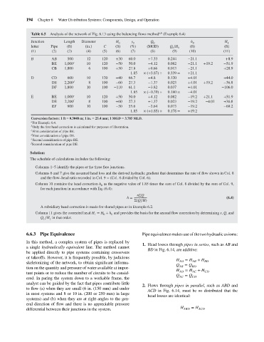
                                               Analysis of the network of Fig. 6.13 using the balancing flows method
                                       Table 6.5
                                                                                     s
                                       Junction
                                                              Diameter
                                                                                                                 h
                                                                              H
                                                      Length
                                                                                                                                H
                                                                                              Q
                                                                                      0
                                                                                                                                  1
                                                                                               0
                                                                                                                 0
                                                                               0
                                                                                    (%)
                                                                                            (MGD)
                                                       (ft)
                                                                                                       Q /H
                                                                (in.)
                                                Pipe
                                                                        C
                                                                              (ft)
                                                                                                                                (ft)
                                       letter
                                                                                                                (ft)
                                                                                                           0
                                                                                                        0
                                                                                     (7)
                                                                              (6)
                                                                                                                                (11)
                                                                                              (8)
                                                                        (5)
                                                                (4)
                                       (1)
                                                                                                        (9)
                                                       (3)
                                                (2)
                                                                                                                (10)
                                                                                             +7.33
                                                                                    60.0
                                                                              +30
                                                                       120
                                                       500
                                                                12
                                                AB
                                       B
                                                                                                                                 +8.9
                                                                                                      0.244
                                                          c
                                                                                                               −21.1
                                                                                                      0.082
                                                                10
                                                                                                                                −51.9
                                                                              −50
                                                                       120
                                                                                    50.0
                                                                                             −4.12
                                                BE
                                                      1,000
                                                                                                               −21.1
                                                                                                                                +28.9
                                                                                    27.8
                                                                       100
                                                                 6
                                                                                             +0.66
                                                                              +50
                                                CB
                                                      1,800
                                                                                                      0.013
                                                                                           × (+3.87) ÷
                                                                                                      0.339 =
                                                                                                               +21.1
                                                                                     1.85
                                                CD
                                                                                                                                +44.0
                                                                              +40
                                                                                                               +4.01
                                                                       120
                                       D
                                                                                             +4.8
                                                                                                      0.120
                                                       600
                                                                10
                                                                                    66.7
                                                          d
                                                                                                      0.023
                                                                                    27.3
                                                                                                               +4.01
                                                                                                                      +19.2
                                                                                                                                −36.8
                                                                                             −1.37
                                                                       100
                                                DE
                                                                 8
                                                      2,200
                                                                              −60
                                                                10
                                                DF  Water Distribution Systems: Components, Design, and Operation a,b  (Example 6.4)  −21.1  +19.2  −106.0
                                                      1,800
                                                                                                      0.037
                                                                       100
                                                                             −110
                                                                                                               +4.01
                                                                                    61.1
                                                                                             −3.82
                                                                                     1.85  × (−0.39) ÷  0.180 =  −4.01
                                       E        BE    1,000 e   10     120    +50   50.0     +4.12    0.082    −19.2  +21.1     +51.9
                                                DE    2,200 f    8     100    +60   27.3     +1.37    0.023    −19.2   −4.01    +36.8
                                                EF     900      10     100    −50   55.6     −3.64    0.073    −19.2            −69.2
                                                                                     1.85  × (+1.85) ÷  0.178 =  +19.2
                                       Conversion factors: 1 ft = 0.3048 m; 1 in. = 25.4 mm; 1 MGD = 3.785 MLD.
                                       a For Example 6.4.
                                       b Only the first head correction is calculated for purposes of illustration.
                                       c First consideration of pipe BE.
                                       d First consideration of pipe DE.
                                       e Second consideration of pipe BE.
                                       f
                                       Second consideration of pipe DE.
                                      Solution:
                                      The schedule of calculations includes the following:
                                         Columns 1–5 identify the pipes at the three free junctions.
                                         Columns 6 and 7 give the assumed head loss and the derived hydraulic gradient that determines the rate of flow shown in Col. 8
                                           and the flow–head ratio recorded in Col. 9 = (Col. 8 divided by Col. 6).
                                         Column 10 contains the head correction h as the negative value of 1.85 times the sum of Col. 8 divided by the sum of Col. 9,
                                                                       0
                                           for each junction in accordance with Eq. (6.4):
                                                                                        nΣQ
                                                                                   h =                                           (6.4)
                                                                                      Σ(Q∕H)
                                           A subsidiary head correction is made for shared pipes as in Example 6.2.
                                         Column 11 gives the corrected head H = H + h and provides the basis for the second flow correction by determining s, Q,and
                                                                    1   0   0
                                           Q ∕H in that order.
                                               1
                                            1
                                    6.6.3 Pipe Equivalence                                Pipe equivalence makes use of the two hydraulic axioms:
                                    In this method, a complex system of pipes is replaced by
                                                                                          1. Head losses through pipes in series, such as AB and
                                    a single hydraulically equivalent line. The method cannot
                                                                                             BD in Fig. 6.14, are additive:
                                    be applied directly to pipe systems containing crossovers
                                    or takeoffs. However, it is frequently possible, by judicious
                                                                                                          H AD  = H AB  + H BD
                                    skeletonizing of the network, to obtain significant informa-
                                                                                                          Q AB  = Q BD
                                    tion on the quantity and pressure of water available at impor-
                                                                                                          H   = H   + H
                                    tant points or to reduce the number of circuits to be consid-          AD    AC    CD
                                                                                                          Q   = Q
                                    ered. In paring the system down to a workable frame, the               AC    CD
                                    analyst can be guided by the fact that pipes contribute little
                                                                                          2. Flows through pipes in parallel, such as ABD and
                                    to flow (a) when they are small (6 in. (150 mm) and under
                                                                                             ACD in Fig. 6.14, must be so distributed that the
                                    in most systems and 8 or 10 in. (200 or 250 mm) in large
                                                                                             head losses are identical:
                                    systems) and (b) when they are at right angles to the gen-
                                    eral direction of flow and there is no appreciable pressure
                                                                                                            H    = H
                                    differential between their junctions in the system.                      ABD    ACD
   211   212   213   214   215   216   217   218   219   220   221