Page 268 - Water Engineering Hydraulics, Distribution and Treatment
P. 268

246
                                                   Pumping, Storage, and Dual Water Systems
                                          Chapter 8
                                                    2
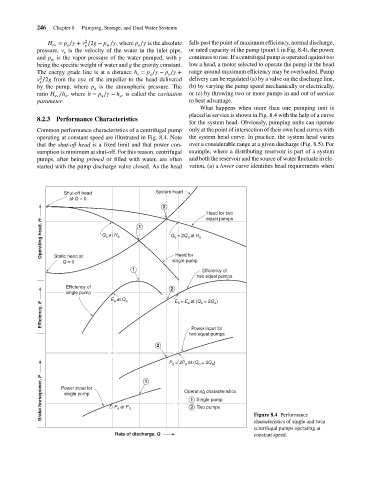
                                                                                       falls past the point of maximum efficiency, normal discharge,
                                        H = p ∕   + v ∕2g − p ∕  , where p ∕   is the absolute
                                         sv
                                              s
                                                           w
                                                                      s
                                                    s
                                                                                       or rated capacity of the pump (point 1 in Fig. 8.4), the power
                                    pressure, v is the velocity of the water in the inlet pipe,
                                             s
                                                                                       continues to rise. If a centrifugal pump is operated against too
                                    and p is the vapor pressure of the water pumped, with   
                                         w
                                                                                       low a head, a motor selected to operate the pump in the head
                                    being the specific weight of water and g the gravity constant.
                                                                                       range around maximum efficiency may be overloaded. Pump
                                    The energy grade line is at a distance h = p ∕   − p ∕   +
                                                                          a
                                                                     s
                                                                                s
                                     2
                                                                                       delivery can be regulated (a) by a valve on the discharge line,
                                    v ∕2g from the eye of the impeller to the head delivered
                                     s
                                                                                       (b) by varying the pump speed mechanically or electrically,
                                    by the pump, where p is the atmospheric pressure. The
                                                       a
                                                                                       or (c) by throwing two or more pumps in and out of service
                                    ratio H ∕h , where h = p ∕   − h , is called the cavitation
                                                                s
                                                          a
                                              s
                                          sv
                                                                                       to best advantage.
                                    parameter.
                                                                                          What happens when more than one pumping unit is
                                                                                       placed in service is shown in Fig. 8.4 with the help of a curve
                                    8.2.3 Performance Characteristics
                                                                                       for the system head. Obviously, pumping units can operate
                                    Common performance characteristics of a centrifugal pump  only at the point of intersection of their own head curves with
                                    operating at constant speed are illustrated in Fig. 8.4. Note  the system head curve. In practice, the system head varies
                                    that the shut-off head is a fixed limit and that power con-  over a considerable range at a given discharge (Fig. 8.5). For
                                    sumption is minimum at shut-off. For this reason, centrifugal  example, where a distributing reservoir is part of a system
                                    pumps, after being primed or filled with water, are often  and both the reservoir and the source of water fluctuate in ele-
                                    started with the pump discharge valve closed. As the head  vation, (a) a lower curve identifies head requirements when
                                             Shut-off head                  System head
                                               at Q = 0
                                                                              2
                                                                                            Head for two
                                                                                            equal pumps
                                      Operating head, H   Q a  at H a  1        Q b  = 2Q a  at H a
                                                                                  Head for
                                          Static head at
                                             Q = 0                               single pump
                                                                    1                      Efficiency of
                                                                                         two equal pumps
                                              Efficiency of                     2
                                              single pump
                                                             E a  at Q a          E b  = E a  at (Q b  = 2Q a )
                                      Efficiency, E
                                                                                       Power input for
                                                                                      two equal pumps
                                                                            2
                                                                                P b  = 2P a  at (Q b  = 2Q a )
                                      Brake horsepower, P  Power input for  P a  at P d  1  Operating characteristics
                                             single pump
                                                                                         Single pump
                                                                                       1
                                                                                         Two pumps
                                                                                       2
                                                                                                            Figure 8.4 Performance
                                                                                                            characteristics of single and twin
                                                                                                            centrifugal pumps operating at
                                                              Rate of discharge, Q                          constant speed.
   263   264   265   266   267   268   269   270   271   272   273