
Page 269 - Water Engineering Hydraulics, Distribution and Treatment
P. 269
247
8.2 Pump Characteristics
120
in the system head at different rates of flow. In these cir-
Tank full, source
110
cumstances, the head curve is nearly horizontal, and the
discharge of parallel pumps is substantially additive. This
100
is common in wastewater pumping stations in which the
90
flow is lifted from a lower to an immediately adjacent higher
80
level. Examples are pumping stations along interceptors or at
Pumps
2 and 3
outfalls.
Total head (ft)
70
Pumps
By contrast, friction may control the head on pumps dis-
60
charging through long force mains, and it may not be feasible
3
to subdivide flows between pumping units with reasonable
Tank empty,
Pumps
50
1 and 2
source at
2
efficiency. Multispeed motors or different combinations of
high level Pump Pump at low level 1 and 3 and discharge piping, for example—there is little change
40 Pump Range in
1 system head pumps and motors may then be required.
30 Because flows from a number of pumps may have to
Minimum demand Normal demand Maximum demand
20 be fed through a different piping system than flows from
any single unit, it may be necessary to develop “modified”
10 characteristic curves that account for losses in different com-
0 binations of piping.
0 10 20 30 40 50 60 Centrifugal pumps are normally operated with discharge
Rate of pumping (MGD )
velocities of 5–15 ft/s (1.5–4.6 m/s). The resulting average
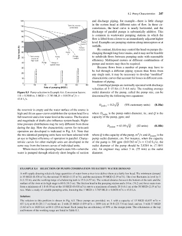
Figure 8.5 Pump selection in Example 8.4. Conversion factors: outlet diameter of the pump, called the pump size, can be
3
1ft = 0.3048 m; 1 MGD = 3.785 MLD = 0.0438 m ∕s = determined by the following two equations:
43.8L∕s.
√
D podin = 0.2 Q (US customary units) (8.18a)
the reservoir is empty and the water surface of the source is
high and (b) an upper curve establishes the system head for a where D podin is the pump outlet diameter, in.; and Q is the
full reservoir and a low water level at the source. The location capacity of the pump, gpm; and
and magnitude of drafts also influence system heads. Night-
time pressure distributions may be very different from those √
D = 63.95 Q (SI units) (8.18b)
during the day. How the characteristic curves for twin-unit podcm
operation are developed is indicated in Fig. 8.4. Note that
3
the two identical pumping units have not been selected with where Q is the capacity of the pump, m ∕s; and D podcm is the
an eye to highest efficiency of operation in parallel. Charac- pump outlet diameter, cm. For instance, when the capacity
3
teristic curves for other multiple units are developed in the of the pump is 200 gpm (0.01262 m ∕s = 12.62 L∕s), the
same way from the known curves of individual units. outlet diameter of the pump should be 2.8284 in. (7.1841
Where most of the operating head is static lift—when the cm). An engineer may select 3 in. (75 mm) as the outlet
water is pumped through relatively short lengths of suction diameter.
EXAMPLE 8.4 SELECTION OF PUMPS COMBINATION TO SATISFY WATER DEMAND
A mill supply drawing relatively large quantities of water from a river is to deliver them at a fairly low head. The minimum demand
3
3
3
is 10 MGD (0.438 m /s), the normal 35 MGD (1.53 m /s), and the maximum 50 MGD (2.19 m /s). The river fluctuates in level by 5
ft (1.52 m), and the working range of a balancing tank is 15 ft (4.57 m). The vertical distance between the bottom of the tank and the
surface of the river at its high stage is 60 ft (18.3 m). The friction head in the pumping station and a 54 in. (76.2 cm) force main rises
3
3
from a minimum of 1 ft (0.30 m) at the 10 MGD (0.438 m /s) rate to a maximum of nearly 20 ft (6.1 m) at the 50 MGD (2.19 m /s)
3
rate. Make a study of suitable pumping units, knowing that 1 MGD = 3.785 MLD = 0.0438 m /s = 43.8 L/s.
Solution:
3
The solution to this problem is shown in Fig. 8.5. Three pumps are provided: no. 1 with a capacity of 15 MGD (0.657 m /s =
3
657 L/s) at 66 ft (20.117 m) head; no. 2 with 25 MGD (1.059 m /s = 1059 L/s) at 78 ft (23.774 m) head; and no. 3 with 37 MGD
3
(1.62 m /s = 1620 L/s) at 84 ft (25.6 m) head. Each pump has an efficiency of 89% at the design point. The efficiencies at the top
and bottom of the working range are listed in Table 8.1.