
Page 264 - Water Engineering Hydraulics, Distribution and Treatment
P. 264
242
Chapter 8
Pumping, Storage, and Dual Water Systems
Figure 8.2 General view of the pumping station Van Sasse in
Grave, the Netherlands (Source: http://en.wikipedia.org/wiki/
Image:Gemaal_van_sasse.jpg).
kilowatt). For purposes of comparison, pumps of given geo-
metrical design are also characterized by their specific speed
N , the hypothetical speed of a homologous (geometrically
s
similar) pump with an impeller diameter D such that it will
Figure 8.1 Pumping station Van Sasse in Grave, the Netherlands discharge 1 gpm (3.78 L/m) against a 1 ft (0.30 m) head.
(Source: http://en.wikipedia.org/wiki/Image:Gemaal_van Because discharge varies as the product of area and velocity,
2
_sasse_interieur.jpg). and velocity varies as H 1/2 , Q varies as D H 1/2 . But velocity
Elevation of pressure energy grade line
2
v d /2g
Elevation of hydraulic grade line
p d /γ
Pressure
gauge
p d
Outlet through
Pressure or
vacuum gauge check valve and
gate valve
p s
z d to system
Datum
Suction energy plane
grade line z s
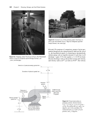
Figure 8.3 Head relationships in
/γ pumping systems. System head II
p s
2
= (z − z ) + (p ∕ − p ∕ ) + (v ∕2g −
d
s
s
d
d
2
v ∕2g). For suction lift, p ∕ and z are
Inlet through strainer s s s
2
and foot valve (where negative, and v ∕2g is positive. For
s
2
v s /2g 2
needed) from source suction pressure, p ∕ and v ∕2g are
s
s
positive, and z is negative.
s