
Page 259 - Water Engineering Hydraulics, Distribution and Treatment
P. 259
237
Problems/Questions
Table 7.22
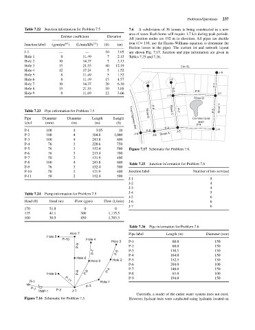
area of town. Each home will require 1.7 L/s during peak periods.
Elevation
Emitter coefficient
All junction nodes are 192 m in elevation. All pipes are ductile
iron (C= 130; use the Hazen–Williams equation to determine the
0.5
0.5
(L/min/kPa )
Junction label
(m)
(gpm/psi )
friction losses in the pipe). The current lot and network layout
—
10
3.05
—
J-1
are shown Fig. 7.17. Junction and pipe information are given in
8
Hole 1
11.49
2.13
7
Tables 7.25 and 7.26.
10
2.13
7
14.37
Hole 2
21.55
40
15
Hole 3
Elm St.
12
5
1.52
Hole 4
17.24
J-8
11.49
Hole 5
1.52
5
8
4.57
15
11.49
8
Hole 6
J-2
J-7
14.37
6.10
Hole 7 Junction information for Problem 7.5 (ft) 12.19 7.6 A subdivision of 36 homes is being constructed in a new
20
10
P-1
Hole 8 15 21.55 10 3.05
P-9
Hole 9 8 11.69 12 3.66 J-1
P-8
J-3
Street D
Street E
P-6
Table 7.23 Pipe information for Problem 7.5 Street B Street C P-7 P-5
Pipe Diameter Diameter Length Length Town highway #64 Common land
label (mm) (in) (m) (ft) open
P-4
P-3
P-1 100 4 3.05 10 P-2 J-5 J-4
P-2 100 4 304.8 1,000 J-9 J-6 Street A
P-3 100 4 243.8 800
P-4 76 3 228.6 750
P-5 76 3 152.4 500 Figure 7.17 Schematic for Problem 7.6.
P-6 76 3 213.4 700
P-7 50 2 121.9 400
P-8 100 4 243.8 800
Table 7.25 Junction information for Problem 7.6
P-9 76 3 152.4 500
P-10 50 2 121.9 400 Junction label Number of lots serviced
P-11 50 2 152.4 500
J-1 5
J-2 4
J-3 4
Table 7.24 Pump information for Problem 7.5 J-4 5
J-5 6
Head (ft) Head (m) Flow (gpm) Flow (L/min) J-6 6
J-7 6
170 51.8 0 0
135 41.1 300 1,135.5
100 30.5 450 1,703.3
Table 7.26 Pipe information for Problem 7.6
Hole 7 Pipe label Length (m) Diameter (mm)
Hole 8
P-10 Hole 4
Hole 3 P-1 60.0 150
P-9 P-2 60.0 150
P-7 P-5 P-3 110.5 150
Hole 6 P-4 164.0 150
Hole 5 Hole 2 P-5 152.5 150
P-6 204.0 100
P-8 P-6 P-4 P-7 148.0 150
Hole 9 P-8 61.0 100
P-9 194.0 150
P-11
R-1 Hole 1
P-3
P-1 P-2
PMP-1 J-1
Currently, a model of the entire water system does not exist.
Figure 7.16 Schematic for Problem 7.5. However, hydrant tests were conducted using hydrants located on